
Audio Memo Alert Circuit

The described device functions as a reminder system that utilizes a simple circuit to detect the presence of paper notes or memos. The core mechanism involves two conductive fingers, which can be made from materials such as metal or conductive plastic. When a paper note is introduced between these fingers, it disrupts the electrical circuit, triggering a response in the system.
The circuit operates with a pair of terminals, designated as Ul-a, which are in a low state when the circuit is closed. When a note is inserted, the physical separation caused by the note leads to an interruption in the circuit, which causes the output of Ul-a to switch to a high state. This change can be used to activate various outputs, such as visual indicators (LEDs), audible alarms, or even notifications to a connected system.
The device aims to enhance information transmission by allowing users to carry articles or notes that can be easily detected and acknowledged by the system. This can be particularly useful in environments where reminders or notifications are crucial, such as in offices or educational settings.
For any inquiries related to the content of the articles, copyright issues, or other concerns, users are encouraged to reach out via the provided email address. It is important to address these matters promptly, as there is a specified timeframe for resolution.This device prevents paper notes and memos from being overlooked. A paper note placed between two fingers made of a conducting material (metal or conductive plastic) breaks the circuit, allowing pair 1 of Ul-a to go high. We aim to transmit more information by carrying articles. Please send us an E-mail to wanghuali@hqew. net within 15 days if we a re involved in the problems of article content, copyright or other problems. We will delete it soon. 🔗 External reference
Related Circuits

In this lab, flip-flops will be utilized. Xilinx provides a comprehensive library of sequential circuits, which is recommended for circuit searches: Xilinx Reference Library. The objective of this lab is to implement a sequential circuit that controls three LEDs:...

The 450/800Hz oscillation circuit depicted in the figure utilizes transformer coupling. The frequency conversion is achieved by varying the inductance through a variable filter tap (T1). When the switch control signal (S) is set to position 1, the oscillator...

A speaker system can be safeguarded against amplifier failure by detecting DC voltages on the speaker line (a-b). The circuit is capable of sensing both positive and negative DC voltages. In such instances, a relay activates to disconnect the...
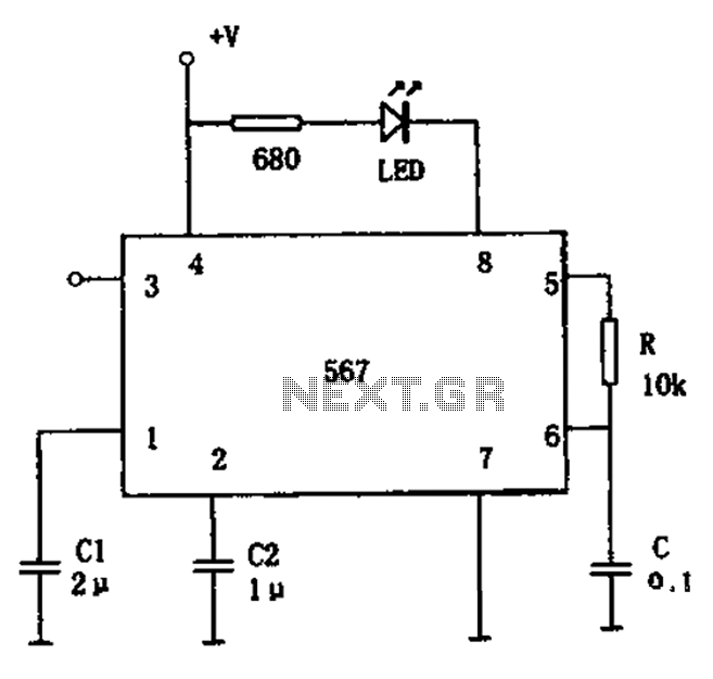
The FM demodulation circuit is illustrated in Figure 567. The FM signal is input at pin 3, and the demodulated signal is output from pin 5. The center frequency of the FM demodulation circuit is determined by the formula...

A siren circuit diagram that generates a strong, high-power siren or alarm sound using complementary transistor pairs BC 557 and BC 337, arranged as an oscillator. The described siren circuit employs a pair of complementary transistors, BC 557 (a PNP...

All distances mentioned can vary depending on the infrared transmitting and receiving LEDs used and are significantly affected by the color of the reflecting surface. Black surfaces greatly reduce the device's sensitivity. This circuit can also be applied in...