
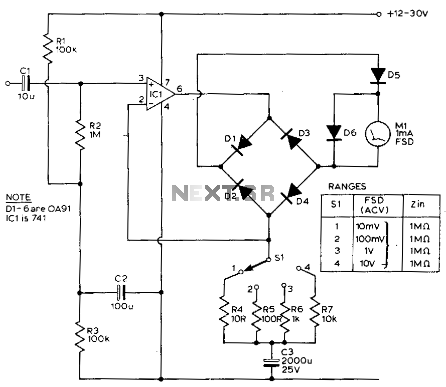
Audio-millivoltmeter

Capacitor C4 couples the output of U1 to a simple attenuator, which provides a loss of 0 dB, 20 dB, or 40 dB, depending on the setting of range switch S1. The circuit's sensitivity is 10 V rms for full-scale deflection, allowing the attenuator to offer additional ranges of 100 mV and 1 V rms. The attenuator output is connected through capacitor C5 to a common-emitter amplifier Q1, which features a high voltage gain of 40. To achieve linear scaling on the meter, an active-rectifier circuit is implemented using U2. The IC is connected so that its non-inverting input is biased to the 0 V bus via R7. Capacitor C6 couples the output of Q1 to the non-inverting input of U2, while C7 serves as the compensation capacitor for U2. The voltage gain of U2 is determined by the resistance difference between the output and the inverting input, as well as between the inverting input and the ground bus. One resistance comprises the diode-bridge rectifier D1 through D4, while the other is formed by resistor R5. This circuit maintains a nearly flat frequency response up to approximately 200 kHz.
The circuit described utilizes several key components to achieve its functionality. Capacitor C4 serves as a coupling capacitor, allowing AC signals to pass while blocking DC offsets, which is essential for interfacing between the output of operational amplifier U1 and the attenuator. The attenuator, controlled by range switch S1, provides selectable attenuation levels, enabling flexibility in signal measurement. The sensitivity of the circuit ensures that a full-scale deflection corresponds to an input of 10 V rms, while additional ranges of 100 mV and 1 V rms are facilitated by the attenuator's design.
The output from the attenuator is then coupled through capacitor C5 to the base of common-emitter amplifier Q1. This amplifier configuration is known for its high voltage gain, which in this case is set to 40, effectively amplifying the signal before it is processed further. The active-rectifier circuit, built around operational amplifier U2, is crucial for converting the amplified AC signal into a DC voltage that can be accurately displayed on a meter. The non-inverting input of U2 is biased to the 0 V reference via resistor R7, ensuring stable operation.
Capacitor C6 plays a vital role by coupling the output of Q1 to the non-inverting input of U2, facilitating signal transfer while maintaining the desired frequency characteristics. Capacitor C7, as the compensation capacitor, helps stabilize the operational amplifier, enhancing performance by reducing the effects of phase shift and ensuring a stable gain.
The voltage gain of U2 is determined by the resistive network formed between the output and the inverting input, as well as between the inverting input and the ground bus. The diode-bridge rectifier, composed of diodes D1 through D4, contributes to the rectification process by allowing current to flow in one direction, thus converting the AC signal to a pulsating DC signal. Resistor R5 completes the resistive network, setting the gain according to the design requirements.
Overall, this circuit is engineered to maintain a flat frequency response up to approximately 200 kHz, making it suitable for a variety of signal processing applications where accurate measurement and linear scaling are essential.Capacitor C4 couples the output of U1 to a simple attenuator, which is used to provide a loss of 0 dB, 20 dB, or 40 dB, depending on the setting of range switch Sl. The circuits sensitivity is 10-V rms for fullscale deflection, so the attenuator gives additional ranges of 100-mV and 1-V rms.
The attenuator output is connected through capacitor C5 to common-emitter amplifier Q1, which has a high-voltage gain of 40 To get linear scaling on the meter, we have to use an active-rectifier circuit built around U2. That IC is connected so that its noninverting input is biased to the 0-V bus via R7. Capacitor C6 couples the output of Q1 to the noninverting input of U2; C7 is the compensation capacitor for U2. The voltage gain of .U2 is set by the difference in resistance between the output and the inverting input, and between the inverting input and the ground bus.
One resistance is made up of the diode-bridge rectifier D1 through D4, the other by resistor RS. This circuit has a nearly flat frequency response to about 200 kHz.
Related Circuits
This circuit exhibits a flat frequency response from 8 Hz to 50 kHz, maintaining a -3 dB level at the 10 mV range. Furthermore, while the upper frequency limit remains consistent across less sensitive ranges, the lower frequency limit...