
audio notch filter

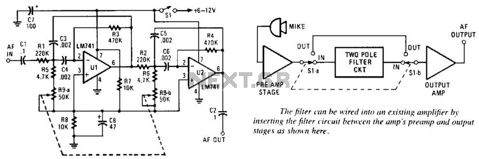
This circuit design incorporates both high-pass and low-pass filter configurations, allowing for versatile frequency response characteristics. The high-pass filter section is designed to attenuate low-frequency signals while allowing high-frequency signals to pass through, effectively removing unwanted low-frequency noise. Conversely, the low-pass filter section is engineered to block high-frequency signals while permitting low-frequency signals to pass, which is useful for filtering out high-frequency interference.
The summing amplifier, which follows the filter sections, combines the outputs of both filters. This amplifier is configured to achieve a gain of approximately 20, meaning that the output signal will be 20 times greater than the input signal. This gain is critical for applications requiring signal amplification after filtering, ensuring that the resultant signal is strong enough for subsequent processing stages.
Additionally, the circuit's design allows for flexibility in its operational mode. By adjusting specific control parameters, the circuit can be reconfigured to function as a band-stop (notch) filter, which is particularly useful for eliminating narrow frequency ranges, such as those associated with hum or interference from specific sources. Alternatively, it can be set up as a band-pass filter, enabling the passage of signals within a certain frequency range while attenuating frequencies outside of this band.
The use of a ±9V DC supply rail voltage provides adequate headroom for the amplifier and filter sections to operate effectively without distortion, ensuring that the integrity of the signal is maintained throughout the processing stages. This circuit is thus well-suited for various applications in audio processing, signal conditioning, and communications systems, where precise control over frequency response is essential.At first glance this circuit looks fairly complex, but when broken down, can be divided into high pass and low pass filter sections followed by a summing amplifier with a gain of around 20 times. Supply rail voltage is +/- 9V DC. The controls may also be adjusted for use as a band stop (notch) filter or band pass filter. 🔗 External reference
Related Circuits

A simple audio watt meter circuit or an audio power or audio level meter circuit with diagram and schematics to measure amplifier audio output power in watts. The audio watt meter circuit is designed to measure the output power of...
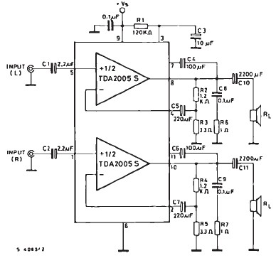
The TDA2005 car audio amplifier circuit is specifically designed for use in devices such as car radios and CD players. This amplifier circuit utilizes the TDA2005 audio integrated circuit (IC), which can deliver a maximum output power of 20...
This variable-frequency audio bandpass filter is constructed using two 741 operational amplifiers (op amps) connected in cascade. Both op amps are configured as identical RC active filters, enhancing the selectivity of the overall circuit. The filter has a tuning...
R1 2.2K 1/4W Resistor, R2 27K 1/4W Resistor, R3, R4 2.2K 1/2W Trimmers (Cermet or Carbon), R5 100R 1/4W Resistor, R6 1K 1/4W Resistor, R7, R8 330R 1/4W Resistors, C1 22 µF 25V Electrolytic Capacitor, C2 47pF 63V Polystyrene...
Explore the power amplifier integrated circuit from National Semiconductor, the LM4780. What is noteworthy about this component is its very low harmonic distortion. Typically, manufacturers specify the maximum power of their products with a harmonic content of around 10%....
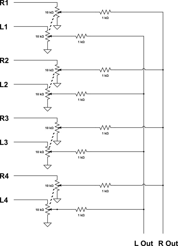
This audio mixer combines multiple audio inputs into a single audio output, equipped with knobs to adjust the volume for each channel. The specific build includes... The audio mixer is designed to facilitate the blending of various audio signals, allowing...