
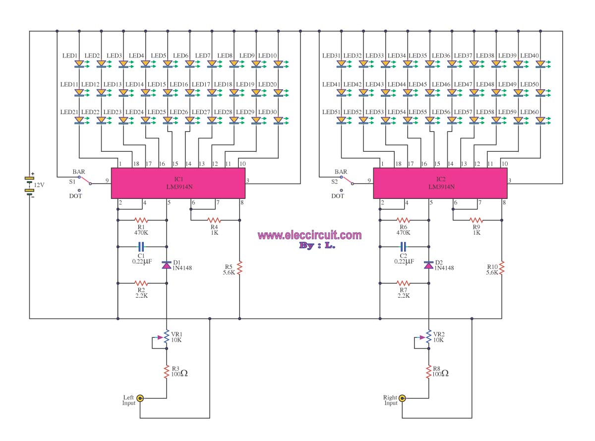
Audio VU Level Meter Circuit with LM324

This electronic circuit schematic presents a versatile design for audio signal processing, incorporating essential components that facilitate the modulation of audio levels through LED indicators. The use of 1K resistors serves as a critical element in determining the activation threshold of the LEDs, allowing them to respond dynamically to varying audio levels. It is important to note that while these resistors can be adjusted, exceeding a resistance value of 5K may lead to insufficient current flow, resulting in some LEDs failing to illuminate.
The flexibility of the circuit design is evident in its compatibility with various op-amps beyond the LM324. This adaptability allows users to select an op-amp based on availability or specific performance characteristics while ensuring that the pin configurations are correctly aligned. The inclusion of a 33K resistor is designed to maintain a low input signal level, which is crucial for preventing distortion and ensuring accurate signal processing. As this resistor may not be readily available, substituting with the nearest standard value is permissible, although the impact on performance should be evaluated through testing.
Prototyping the circuit on a breadboard is highly recommended before committing to a PCB layout. This approach allows for real-time adjustments and optimizations, particularly concerning the 33K resistor value, which may require fine-tuning based on the specific application and audio source characteristics. The circuit is configured to receive line-level audio signals, making it suitable for integration with various audio equipment, including Hi-Fi systems. However, modifications can be made to accommodate speaker-level inputs, expanding the circuit's usability.
The audio input configuration is straightforward, with the positive audio signal connected to the main positive rail of the circuit and the negative audio signal designated for input. The inclusion of a 50K potentiometer provides a user-friendly interface for adjusting the circuit's sensitivity, allowing for tailored performance based on individual requirements or environmental conditions. Overall, this schematic serves as a foundational design for audio processing applications, offering opportunities for customization and enhancement based on user needs.Welcome to the weblog where we discuss about electronic circuits schematics, PCB design, diy kits and electronic projects diagrams. The 1K resistors in the circuit are capital so that the LED`s about-face on at altered audio levels. There is no acumen why you can`t change these resistors, although annihilation aloft 5K may account some of the LED
`s to never about-face on. This ambit is calmly abundant with added op-amps, and is not bound to use with the LM324. Pretty abundant any op-amp will assignment as continued as you attending up the pinouts and accomplish abiding aggregate is appropriately connected. The 33K resistor on the schematic is to accumulate the arresting ascribe to the ambit at a low level.
It is absurd you will acquisition a 33K resistor, so the abutting you can get should do. The amount of this resistor may charge to be changed, so it is best you breadboard this ambit afore absolutely amalgam it on PCB. The ambit in it`s accepted anatomy will acquire band akin inputs from sources such as the aux out on a Hi-Fi, all admitting could be calmly adapted to acquire apostle inputs.
The audio + is affiliated to the capital absolute rail, while the audio - is acclimated for arresting input. The 50k pot can be acclimated to alter the acuteness of the circuit. 🔗 External reference
Related Circuits
An inductance meter can be a valuable test instrument for hobbyists. However, few people own them due to their high price. The Inductance Meter Adapter described in this article is a circuit that, when connected to a digital multimeter...
The TDA8581 from Philips Semiconductors is a 1-watt Bridge Tied Load (BTL) audio power amplifier capable of delivering 1 watt output power into an 8 ohm load. The TDA8581 is designed for audio amplification applications, particularly in consumer electronics such...
A VU meter is utilized to display the power level of audio signals and also serves as an aesthetic element. When purchasing a VU meter kit from an electronics store, options include assembling various parts independently or selecting a...
A few years ago, a decision was made to eventually replace a decades-old Nakamichi stereo system with a more mobile-friendly alternative. It became apparent that Class-D and Class-E switching amplifiers, which had been researched in the 1970s, were experiencing...
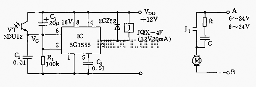
The control circuit consists of an NE555 timer and a phototransistor, along with resistors R1, capacitors C1 and C2, among other components. The photodiodes 3DU12 respond to sunlight by decreasing their resistance, which causes the voltage at the 555...
The opto-isolator LEDs are connected to three wires labeled "FWD," "REV," and "ENA." These wires serve as the interface between the bridge and the microprocessor. It is important to note that there is no "ground" signal present. When connecting...