
Noise-limiter
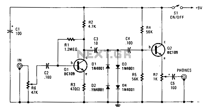
This circuit is powered from the earphone jack of the receiver and is routed to the limiter control R6. It is then amplified by Q1, which is configured as a common-emitter stage with a voltage gain of approximately 10, due to the negative feedback introduced by R3. The output from Q1 is directed to a simple clipping circuit consisting of diodes D1 through D4. The diodes are connected in pairs and function similarly to Zener diodes with an avalanche rating of about 1 V. The two pairs are oriented in opposite polarities, allowing the audio signal to be clipped at approximately 1 V. The signal is subsequently coupled to the output socket via an emitter-follower buffer stage built around Q2, along with an output attenuator control R7.
The circuit begins by receiving an audio signal from the earphone jack of the receiver. This signal is first processed by a limiter control (R6), which helps to prevent signal distortion by limiting the maximum amplitude of the input signal. Following this, the signal is amplified by Q1, a common-emitter transistor configuration. This configuration is chosen for its ability to provide a moderate level of gain while also allowing for the implementation of negative feedback through resistor R3. The feedback effectively stabilizes the gain at around 10, ensuring that the output remains predictable and manageable.
After amplification, the signal is sent to a clipping circuit composed of four diodes (D1 to D4), arranged in two pairs. Each pair of diodes is oriented in opposite polarities, which allows them to clip the audio signal at a threshold of approximately 1 V. This clipping action is crucial for protecting downstream components from excessive voltage levels and for shaping the audio waveform to produce a desired sound characteristic. The diodes operate in a manner similar to Zener diodes, utilizing their avalanche breakdown properties to limit the voltage effectively.
The clipped audio signal is then coupled to the output socket through an emitter-follower buffer stage, which is implemented using Q2. The emitter-follower configuration is advantageous as it provides high input impedance and low output impedance, allowing for effective signal transfer without loading down the previous stage. Additionally, the output attenuator control (R7) is included to provide users with the ability to adjust the output level, ensuring compatibility with various downstream devices and allowing for fine-tuning of the audio signal before it reaches the final output stage.This circuit is fed from the earphone jack of your receiver and goes to limiter control R6 and is then amplified by Ql: a common-emitter stage that has a voltage gain of only about 10, because of the negative feedback introduced by R3. The output of Ql is fed to a simple clipping circuit, consisting of diodes D1 through D4. The diodes, connected in pairs, act like Zeners with an avalanche rating of aboun V. The two pairs are connected opposite in polarity to each other, so that the audio signalis clipped at about 1 V. The signal is then coupled to the output socket through an emitter-follower buffer stage built around QZ and an output attenuator control R7.
🔗 External reference