


Current negative feedback electronic frequency power amplifier circuit
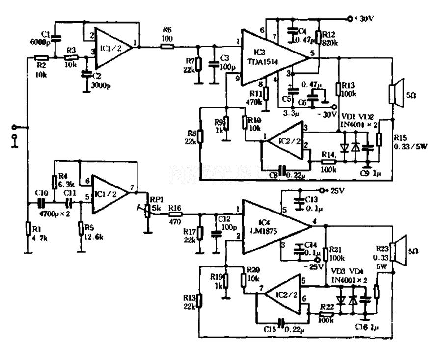
Description: The mechanical and electrical schematic in Figure 5 illustrates a simple circuit comprising several components. The first component is an electronic crossover section utilizing the NE5532 operational amplifier, which is known as the "Emperor of the op-amp." This section forms a typical second-order active filter with its associated RC elements, allowing the signal to be processed before being amplified by subsequent units. The crossover filter operates at a frequency of 3.7 kHz, and adjustments can be made by recalculating the RC elements. The second component is the power amplifier section, which includes the TDA1514 and LM1875 integrated circuits, responsible for amplifying low, medium, and high frequencies. Notably, this amplifier circuit employs a current negative feedback mechanism, differing from traditional voltage feedback systems. Resistors R15 and R23 are part of the feedback loop, where the current flowing through the speakers is sampled and returned to the input of the amplifier. This configuration allows the speaker to act as a part of the negative feedback network, minimizing the effects of the speaker's electro-acoustic impedance and transient characteristics, thereby enhancing sound quality. Additionally, the use of current negative feedback improves the performance of the output power amplifier.
The schematic presented in Figure 5 encompasses a straightforward yet effective design for audio signal processing. The electronic crossover section is pivotal for dividing the audio signal into different frequency bands, ensuring that each band is directed to the appropriate amplifier stage. The NE5532 op-amp, renowned for its low noise and high performance, is configured to create a second-order filter, which is essential for achieving a smooth transition between frequency ranges. The cutoff frequency of 3.7 kHz is a crucial parameter that can be adjusted by modifying the values of the resistors and capacitors in the RC network, allowing for customization based on specific audio requirements.
In the power amplifier section, the TDA1514 and LM1875 are selected for their robustness in handling various frequency ranges. The TDA1514 is particularly effective for driving low frequencies, while the LM1875 excels in mid to high-frequency amplification. The innovative use of current negative feedback in this design stands out, as it enhances the amplifier's ability to respond dynamically to changes in load conditions. By sampling the current flowing through the speakers, the amplifier can make real-time adjustments, thus maintaining optimal performance and reducing distortion.
The feedback mechanism involving resistors R15 and R23 is integral to the circuit's operation. By incorporating the speaker into the feedback loop, the design effectively mitigates issues related to transient response, ensuring that the audio output remains clear and free from unwanted artifacts. This approach not only improves sound quality but also contributes to the overall reliability and efficiency of the amplifier system.
Overall, the schematic in Figure 5 exemplifies a well-thought-out design that leverages advanced electronic components and feedback techniques to deliver high-quality audio performance. The careful selection of components and the innovative feedback strategy are key factors in achieving superior sound reproduction.The mechanical and electrical schematic in Figure 5 112 in FIG. Chant is a schematic diagram of the channel can be seen from the figure, the entire circuit is very simple. It consists of the following components: (1) electronic crossover section 6 ICl as the "Emperor of the op amp," said the NE5532 mouth and around its RC element constitutes a typical second-order filter active input 6 after the signal points rather backward people behind the amplifier units amplify. According to the figure number, according to the crossover filter to 3. 7kHz, To change, simply calculated after changing the filter element can be RC. (2) power amplifier section of the heart IC3 TDA1514. LC4 the LM1875, which are as low, medium and high frequency amplification. It can be seen that the most part of the biggest difference amplifier circuit is that it increases the negative feedback amplifier circuit p general feedback voltage are all used in the form of negative feedback, and this machine is using the current negative feedback.
R15. R23 electricity flowing through the speakers stream sampling, back to the input of the amplifier, the amplifier is driven with a constant current load. Thus, the speaker has become a part of the negative feedback network, you can eliminate the effects of electro-acoustic impedance speaker system transient characteristics, the system transient distortion splash to a minimum, thereby improving the sound quality.
In addition, after using the current negative feedback, the output power amplifier
The schematic presented in Figure 5 encompasses a straightforward yet effective design for audio signal processing. The electronic crossover section is pivotal for dividing the audio signal into different frequency bands, ensuring that each band is directed to the appropriate amplifier stage. The NE5532 op-amp, renowned for its low noise and high performance, is configured to create a second-order filter, which is essential for achieving a smooth transition between frequency ranges. The cutoff frequency of 3.7 kHz is a crucial parameter that can be adjusted by modifying the values of the resistors and capacitors in the RC network, allowing for customization based on specific audio requirements.
In the power amplifier section, the TDA1514 and LM1875 are selected for their robustness in handling various frequency ranges. The TDA1514 is particularly effective for driving low frequencies, while the LM1875 excels in mid to high-frequency amplification. The innovative use of current negative feedback in this design stands out, as it enhances the amplifier's ability to respond dynamically to changes in load conditions. By sampling the current flowing through the speakers, the amplifier can make real-time adjustments, thus maintaining optimal performance and reducing distortion.
The feedback mechanism involving resistors R15 and R23 is integral to the circuit's operation. By incorporating the speaker into the feedback loop, the design effectively mitigates issues related to transient response, ensuring that the audio output remains clear and free from unwanted artifacts. This approach not only improves sound quality but also contributes to the overall reliability and efficiency of the amplifier system.
Overall, the schematic in Figure 5 exemplifies a well-thought-out design that leverages advanced electronic components and feedback techniques to deliver high-quality audio performance. The careful selection of components and the innovative feedback strategy are key factors in achieving superior sound reproduction.The mechanical and electrical schematic in Figure 5 112 in FIG. Chant is a schematic diagram of the channel can be seen from the figure, the entire circuit is very simple. It consists of the following components: (1) electronic crossover section 6 ICl as the "Emperor of the op amp," said the NE5532 mouth and around its RC element constitutes a typical second-order filter active input 6 after the signal points rather backward people behind the amplifier units amplify. According to the figure number, according to the crossover filter to 3. 7kHz, To change, simply calculated after changing the filter element can be RC. (2) power amplifier section of the heart IC3 TDA1514. LC4 the LM1875, which are as low, medium and high frequency amplification. It can be seen that the most part of the biggest difference amplifier circuit is that it increases the negative feedback amplifier circuit p general feedback voltage are all used in the form of negative feedback, and this machine is using the current negative feedback.
R15. R23 electricity flowing through the speakers stream sampling, back to the input of the amplifier, the amplifier is driven with a constant current load. Thus, the speaker has become a part of the negative feedback network, you can eliminate the effects of electro-acoustic impedance speaker system transient characteristics, the system transient distortion splash to a minimum, thereby improving the sound quality.
In addition, after using the current negative feedback, the output power amplifier
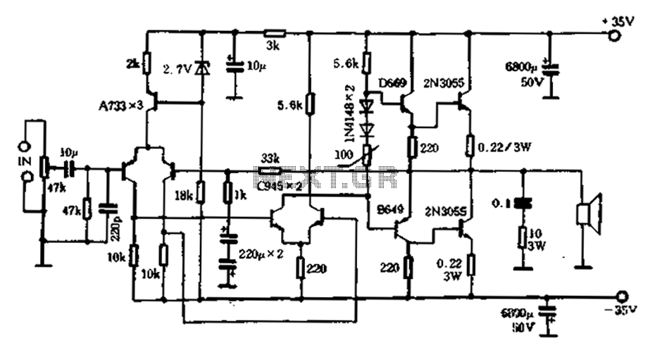
Pre-dividing power amplifier
An active high-power tube operates in the MHz range, priced around 3 to 4 yuan, with a transition frequency (fT) exceeding one-fifth of 50 MHz for similar power tubes. This circuit is designed for high reliability in low-frequency high-power amplifier...
Crossover For Subwoofer
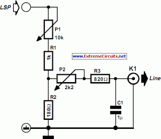
The crossover network is designed for extending an existing audio installation by adding a subwoofer. Often, this subwoofer is a previously unused unit. If its frequency response is adequate, it requires a filter to eliminate any frequencies above approximately 150...
power amp 10 000w circuit diagram
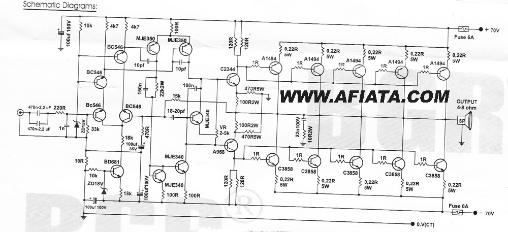
How many speakers can be attached to this amplifier, and what are the impedance and wattage values of these speakers? Please respond to my email. Sir, you made this amplifier, and it works properly for a lifetime. Which transformer is...
Power amplifier
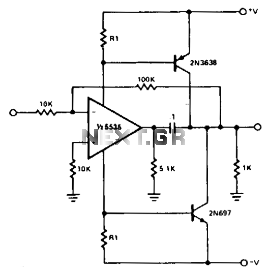
For most applications, the power provided by operational amplifiers (op amps) is adequate. However, there are instances where a greater power handling capability is required. A straightforward power booster that can drive moderate loads utilizes the NE5535 device. Other amplifiers...
Audio Clipping Detector Circuit
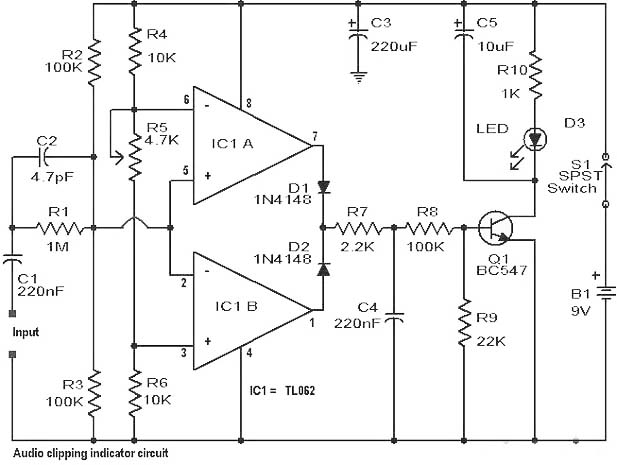
Clipping is a significant issue that leads to distortion in amplifiers. It results in the amplitude level of a waveform dropping abruptly before it reaches its intended limit. This document presents a straightforward circuit designed to detect clipping in a...
Power Amplifier 6
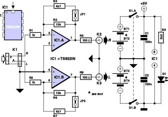
This simple circuit is designed to provide an output power of approximately 1 watt when connected to a 9-volt power supply. The key advantage of this circuit is its use of a dual Darlington configuration, which increases the input impedance...

2M Fet Power Amplifier Circuit
Using a power MOSFET, this amplifier can achieve a 2-W handheld radio power level, increasing it to approximately 10 W on the 2-meter band. A transmission-line RF switch is employed for transmit/receive (T/R) switching.
The described amplifier utilizes a power MOSFET...
150W MP3 Car Amplifier
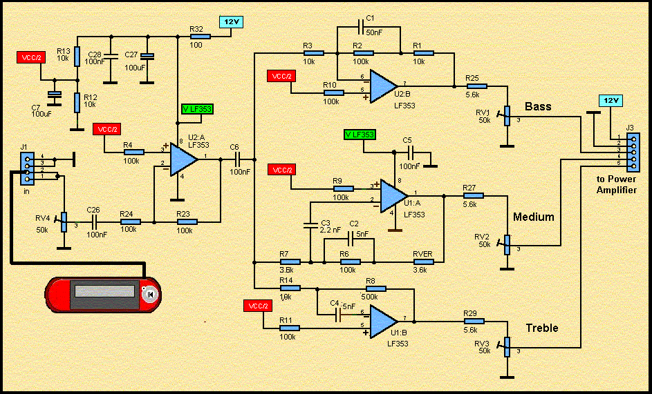
A diagram of an active loudspeaker. The LF353 from National Semiconductor will split the audio signal into three bands. The SANYO LA47536 will amplify these signals. In stereo mode, eight high speakers will create significant sound pressure. The LF353 is...
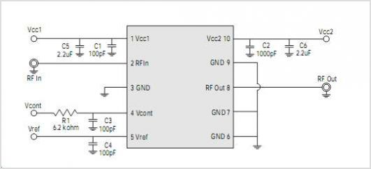
WS2512 4 X 4 Power Amplifier Module
The WSH412 is designed to integrate a Hall sensor with complementary output drivers and a frequency generator on a single chip. It is suitable for applications such as speed measurement, revolution counting, positioning, and DC brushless motors. The device includes...