


Linear optocoupler for instrumentation
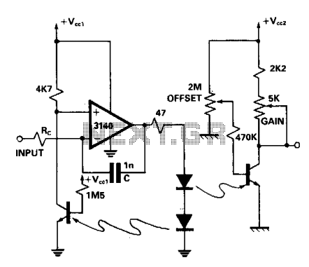
Description: A dual optocoupler is utilized in a configuration that maintains the same current across the LEDs. Assuming comparable optocoupler characteristics, the output voltage must match the non-inverting input voltage. Given that the operational amplifier operates within a closed loop, the output voltage becomes equal to the input voltage. Additionally, the resistor (Rc) and capacitor (C) function as a compensation network to mitigate oscillations.
The dual optocoupler configuration is an essential component in various electronic circuits, particularly in signal isolation and level shifting applications. The optocoupler consists of two light-emitting diodes (LEDs) and photodetectors, allowing electrical isolation between different circuit sections while enabling signal transmission. The configuration ensures that the current flowing through the LEDs is consistent, which is critical for maintaining the integrity of the output signal.
In this setup, the output voltage is designed to be equal to the non-inverting input voltage of the operational amplifier (op-amp). This relationship is significant because it indicates that the op-amp is functioning in a linear region, ensuring accurate amplification or signal processing. The closed-loop configuration of the op-amp further reinforces this behavior, as feedback is employed to stabilize the output voltage, effectively making it track the input voltage closely.
The inclusion of the resistor (Rc) and capacitor (C) as a compensation network is vital for maintaining stability within the circuit. This network helps to dampen potential oscillations that may arise due to the feedback loop. By carefully selecting the values of Rc and C, the designer can tailor the frequency response of the circuit, ensuring that it operates smoothly without unwanted oscillatory behavior.
Overall, this dual optocoupler configuration, combined with the compensation network, provides a robust solution for applications requiring precise signal isolation and control, ensuring reliable performance in various electronic systems.A dual optocoupler is used in a configuration which has the same current throughout as the LEDs. Assuming similar optocoupler features the output voltage must be equal to the non-inverting input voltage. Since the op amp is within a closed loop the output voltage becomes equal to the input voltage. Rc and C perform as a compensation network to prevent oscillations.
The dual optocoupler configuration is an essential component in various electronic circuits, particularly in signal isolation and level shifting applications. The optocoupler consists of two light-emitting diodes (LEDs) and photodetectors, allowing electrical isolation between different circuit sections while enabling signal transmission. The configuration ensures that the current flowing through the LEDs is consistent, which is critical for maintaining the integrity of the output signal.
In this setup, the output voltage is designed to be equal to the non-inverting input voltage of the operational amplifier (op-amp). This relationship is significant because it indicates that the op-amp is functioning in a linear region, ensuring accurate amplification or signal processing. The closed-loop configuration of the op-amp further reinforces this behavior, as feedback is employed to stabilize the output voltage, effectively making it track the input voltage closely.
The inclusion of the resistor (Rc) and capacitor (C) as a compensation network is vital for maintaining stability within the circuit. This network helps to dampen potential oscillations that may arise due to the feedback loop. By carefully selecting the values of Rc and C, the designer can tailor the frequency response of the circuit, ensuring that it operates smoothly without unwanted oscillatory behavior.
Overall, this dual optocoupler configuration, combined with the compensation network, provides a robust solution for applications requiring precise signal isolation and control, ensuring reliable performance in various electronic systems.A dual optocoupler is used in a configuration which has the same current throughout as the LEDs. Assuming similar optocoupler features the output voltage must be equal to the non-inverting input voltage. Since the op amp is within a closed loop the output voltage becomes equal to the input voltage. Rc and C perform as a compensation network to prevent oscillations.
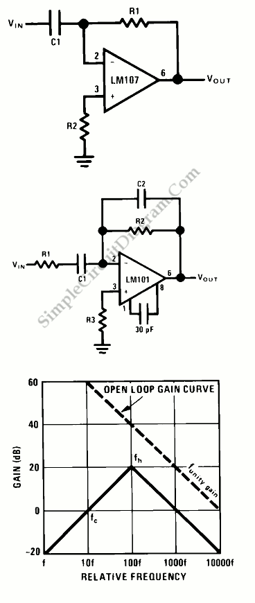
Op-Amp Circuit: Differentiator
This is a differentiator circuit. This circuit can be used to perform differential operations. There are two types of differentiators: the true differentiator and another type.
A differentiator circuit is designed to output a voltage that is proportional to the rate...
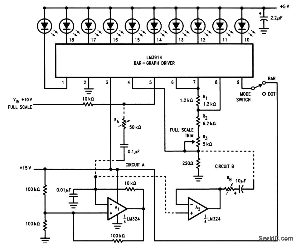
High resolution dithering bar graph display
This circuit is an enhanced version of the display shown in Fig. 3-28, utilizing a triangular-wave oscillator. When the resistor RA is adjusted correctly, each incremental change in the input voltage (VIN) can be detected, allowing the glow from each...
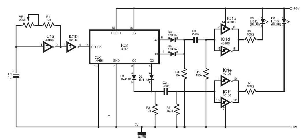
Police Car Lights with LEDs
This circuit simulates the flashing lights of a police car, similar to those seen on British police vehicles. The operational amplifier IC1a functions as a square wave oscillator, with an adjustable frequency controlled by the variable resistor VR1 to achieve...
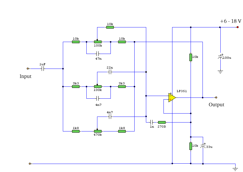
3 Band Graphic Equalizer
This simple equalizer utilizes a single operational amplifier (op-amp) and provides three frequency ranges: low frequency, mid frequency, and high frequency. With the specified component values, it achieves approximately ±20 dB of gain or attenuation at frequencies of 50 Hz,...
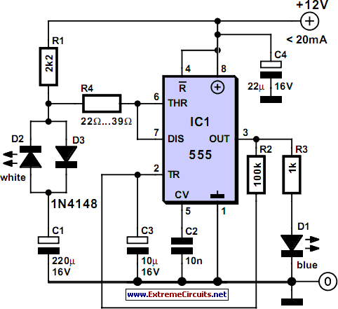
Bluish Flasher
The circuit illustrates how the combination of a blue LED and a white LED can be utilized to create a realistic imitation of a camera flashlight.
The circuit design employs a blue LED and a white LED in conjunction to simulate...

power led flasher
The low-cost and compact circuit presented here serves as a highly power-saving flashing LED indicator. While most LEDs typically fail to operate below 2 volts, with a forward voltage of at least 1.6 volts, this flasher can function using a...
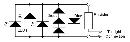
Using white LEDs
The yellow LEDs are on a small PCB, which are easy to remove. On the PCB there are 3 yellow LEDs and 4 diodes. Pictures of the PCB can be seen here: Top-side - Bottom-side. The schematic is as follows:...
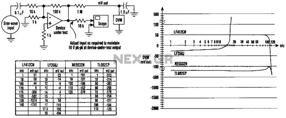
Check For Op-Amp Dc Offset Shift Circuit
The DC values of op-amp offsets cannot always be assumed to remain constant when delivering AC outputs. No device is perfectly symmetrical in terms of maximum positive slew rate compared to maximum negative slew rate. As a result, there exists...
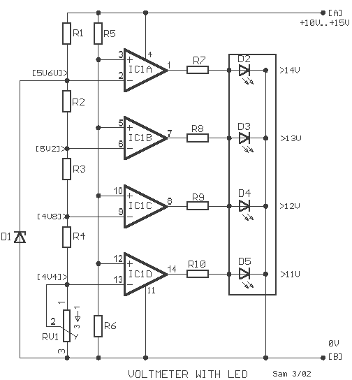
LED Voltmeter for Cars
The circuit is a comparator that can measure the voltage of a car battery in steps of 1 Volt. The voltage is determined after comparing the voltage of the battery, which is applied to the inverting inputs of amplifiers, with...