
Auto-alarm

In operation, the alarm circuit allows a 0-47 second time delay, as determined by the R1/C1 combination, after the switch is armed to allow the vehicle's motion sensor to settle down. This provides time to retrieve items, such as groceries, from the trunk without the inconvenience of managing both the groceries and the key switch simultaneously. During the time delay, half of LED1, which is a single bi-colored, three-legged common cathode device, lights up green. Simultaneously, pins 8 and 4 of U2 (a 555 oscillator/timer) are held low by U1 (a 3905 oscillator/timer), keeping the alarm silent. Once the delay is over, LED1 turns red, indicating that the circuit is armed.
At that point, a ground at pin 2 of U2 forces pin 3 of U2 high, closing the contacts of K1 and activating the siren for a duration determined by R4 and C2. After this time has elapsed, pin 3 is pulled low, K1 opens, and the circuit is ready to be armed again. The circuit can be manually reset by simply opening and closing the key switch. Potentiometer R3 adjusts the LED's illumination intensity. Diode D1 ensures that the green segment of LED1 is completely extinguished when Q1 is turned on, which changes the LED to red. Resistors R4 and R5 must be connected to the +V bus, rather than to pin 7 of U1, to prevent U2 from triggering itself each time the initial delay concludes.
The alarm circuit is designed to enhance user convenience and security by integrating a delay mechanism that accommodates the user's needs while ensuring effective operation. The time delay, adjustable between 0 to 47 seconds, is achieved through the resistor-capacitor network formed by R1 and C1. This configuration allows for the gradual stabilization of the vehicle's motion sensor, ensuring that false alarms are minimized.
LED1 serves a dual purpose: it provides a visual indication of the circuit's status and informs the user when the alarm is armed. The bi-colored nature of the LED enhances the clarity of the status indication, with green signaling readiness and red indicating that the alarm is active. The integration of the 555 timer (U2) and the 3905 timer (U1) is crucial for the operation of the alarm system. U1 ensures that the alarm remains inactive during the delay period by holding specific pins low, thus preventing any unintended triggering.
The siren activation is controlled by the relay K1, which is engaged when pin 3 of U2 goes high. The duration of the siren's sound is determined by the values of R4 and C2, which set the timing for how long the alarm will sound once triggered. The manual reset feature, facilitated by the key switch, allows users to quickly deactivate the system without needing to disconnect power or make complex adjustments.
The potentiometer R3 provides an adjustable brightness feature for LED1, allowing users to customize the visibility of the status indicator based on their preferences or environmental conditions. The inclusion of diode D1 ensures that there is no back-feed of current that could inadvertently light the green segment of the LED when the alarm is armed. This careful consideration in the circuit design helps to maintain clear status indications and reliable operation of the alarm system. Proper connection of resistors R4 and R5 to the +V bus is essential, as incorrect connections can lead to erratic behavior of the circuit, highlighting the importance of meticulous assembly and testing in the design process.In operation. the alarm circuit allows a 0-47 second time delay, as determined by the Rl/Cl combination, after the switch is armed to allow the vehicle"s motion sensor to settle down. This allows you time to get a bag of groceries out of the trunk and not have the hassle of juggling the groceries and the key switch at once.
During the time delay, half of LEDl, which is actually a single, bi-colored, three-legged common cathode device, lights green. At the same time, pins 8 and 4 of U2 (a 555 oscillator/timer) are held low by Ul (a 3905 oscillator/timer), causing the alarm to remain silent.
Once the delay is over, LEDl turns red, indicating that the circuit is armed. At that point, a ground at pin 2 of U2 forces pin 3 of U2 high, closing the contacts of Kl and sounding the siren for a time duration determined by R4 and C2. Once the time has elapsed, pin 3 is pulled low, Kl opens, and the circuit is again ready to go. The circuit can be manually reset by the simple expedient of opening and closing the key switch. Potentiometer R3 controls the LED"s illumination intensity. Diode Dl ensures that the green segment of LED! is fully extinguished when Ql is turned on-which turns the LED to red. Resistors R4 and R5 mustbe connected to the +V bus, not to pin 7 of Ul, otherwise U2 will mysteriously trigger itself each time the initial delay ends.
Related Circuits
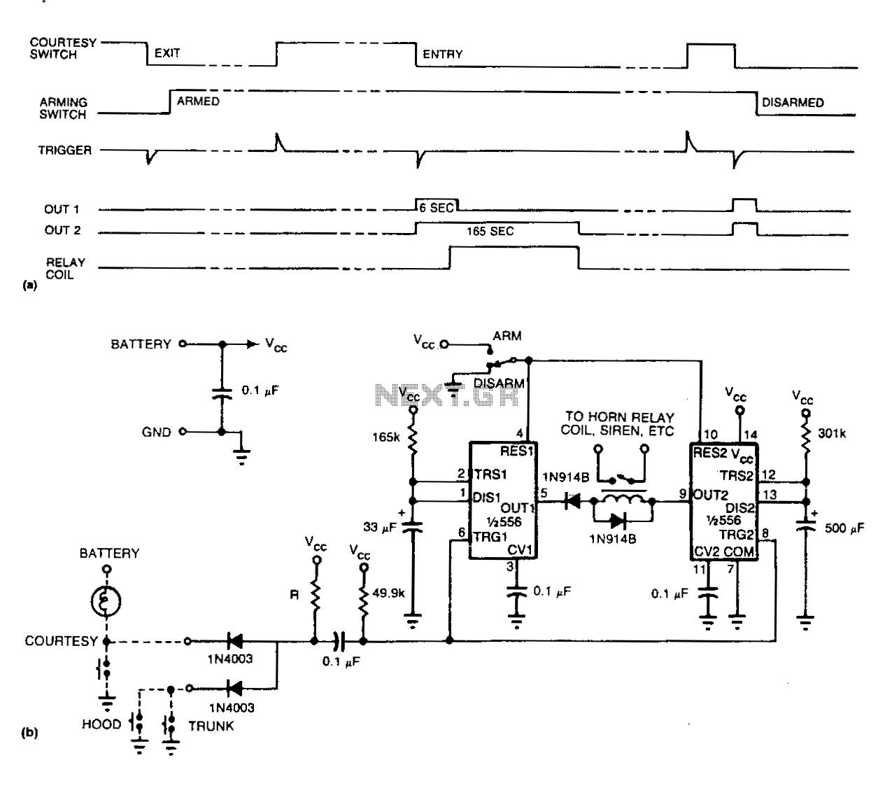
Refer to (a) for the timing information related to the alarm circuit depicted in (b). When departing from the vehicle, the arming switch should be flipped, and the door closed to activate the device. The subsequent opening of an...