
Auto Telephone line Recorder
This circuit is designed to interface a tape recorder with a microphone and remote input to a telephone line, enabling automatic recording of both sides of a conversation. The operation relies on the voltage characteristics of the telephone line. When the phone is on-hook, the line voltage is approximately 48 volts DC, which keeps the field-effect transistor (FET) in an off state. In this state, transistors Q2 and Q3 are also off, preventing any current flow to the tape recorder.
Upon lifting the handset, the phone goes off-hook, causing the line voltage to drop to below 10 volts DC. This change in voltage activates the FET, which in turn switches on transistors Q2 and Q3. The activation of these transistors allows current to flow to the tape recorder, thus enabling it to start recording. It is crucial that the tape recorder is set to record mode at all times to ensure that the conversation is captured.
The circuit requires careful connection to the phone line, necessitating preliminary voltage readings to ascertain the correct polarity before making connections. The power for the entire circuit is derived from the phone line itself, making it a convenient solution for recording telephone conversations without the need for an external power supply. Proper implementation of this circuit can provide a reliable method for recording calls, provided that all components are rated appropriately for the voltages involved and that the circuit is assembled with attention to detail to avoid any potential damage.his circuit will allow you to connect any tape recorder that has a mic and remote input to a phone line and automatically record both sides of a conversation when ever the phone is in use. You will need to take a couple of voltage readings before connecting the circuit. First determine the polarity of your phone line and connect it to the circuit as shown and then determine the polarity of the remote input and connect it to the circuit.
Circuit operation is as follows. When the phone is on hook the voltage across the phone line is about 48volts dc. When the phone is off hook the voltage will drop to below 10volts dc. When the line voltage is at 48volts the FET is off which causes Q2 and Q3 to be off. When the phone is picked up the FET turns on along with Q2 and Q3 which turns your recorder on. The tape recorder must be in the record mode at all times. As you can see the power source for the circuit is the phone line. 🔗 External reference
Related Circuits
XP power plug, FU fuse, ST temperature control, T1 low-voltage transformers, S1, S2 door interlock switch, S3 threshold control switch, RT thermal sensor, K1, K2 relay, EL furnace light, M1 wheel motor, M2 fan motor, T2 high-voltage transformer, C...
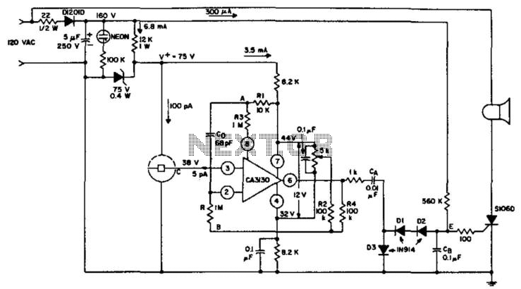
An ionization chamber in conjunction with a high-impedance CA3130 operational amplifier is utilized to detect the presence of smoke. When smoke is detected, the CA3130 ceases oscillation, which in turn triggers the S106D silicon-controlled rectifier (SCR) to sound an...
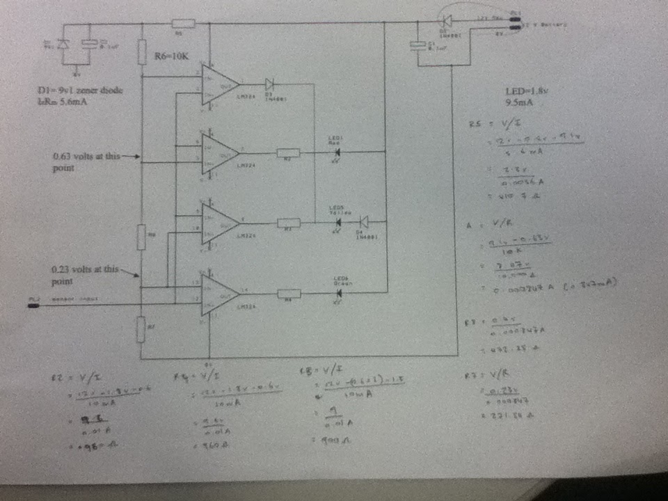
The diagram illustrates the connections for the inputs and outputs of each operational amplifier from the power source, detailing how each operational amplifier is configured to operate individual light-emitting diodes (LEDs). It also includes calculations for determining each resistor...
This instrument is a computer-controlled acoustical angklung designed and built in 2000. In 2006, it underwent a major hardware upgrade. The anklungs are constructed from hardened brass and are tuned to a western scale covering two octaves. The instrument...
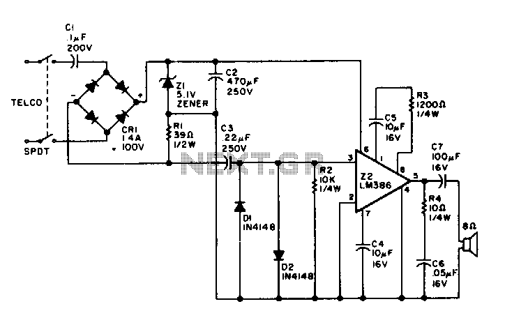
Utilizing rectified audio as a power supply, this monitor will transmit the audio from the telephone line to an 8-ohm speaker. The circuit leverages the concept of rectifying audio signals to provide a usable power supply for driving an 8-ohm...
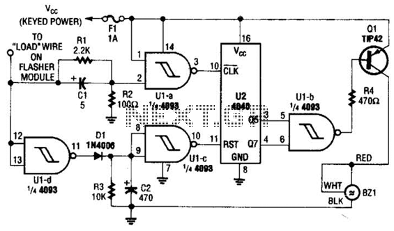
This circuit counts the flashes of turn signals. After approximately 70 flashes, a chime sounds to remind the driver to deactivate the turn signal. The period can be altered by using different taps on U2 if desired. BZ1 serves...