
Automatic 12V Lead Acid Battery Charger

The described circuit involves a battery charger designed to accommodate various types of lead-acid batteries, including flooded, gel, and AGM configurations. The core of the design is a transformer (T1) that converts the mains voltage (either 120V or 220V) to a lower AC voltage, typically around 12V for standard charging applications. The transformer's secondary output can be increased to 16V-18V to cater to specialized 16V batteries often found in competitive racing environments.
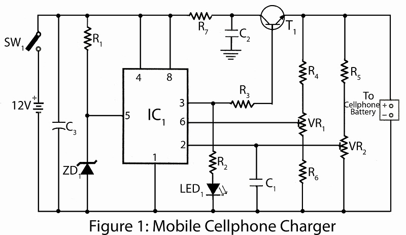
The adjustable resistor, labeled R2, functions as a voltage divider, allowing the user to fine-tune the output voltage of the charger to meet the specific requirements of different battery types. For flooded and gel batteries, the output is set to approximately 13.8V, while AGM batteries, which are frequently cycled, require a higher voltage in the range of 14.5V to 14.9V. The potentiometer's midpoint setting serves as a starting point for configuration, ensuring that the user can easily make adjustments.
The incorporation of a voltmeter into the circuit is crucial for monitoring the charging process. By connecting the voltmeter to the charger's output, the user can observe the voltage increase as the battery charges. Once the desired voltage is reached, the potentiometer is adjusted until the LED indicator lights up steadily, signifying that the charger is correctly set for the battery type in use.
To enhance usability, the design allows for the potentiometer to be mounted externally on the charger case, with each voltage setting clearly marked. This feature simplifies the process of switching between different battery types, ensuring that users can quickly adjust the charger without needing to open the case.
Overall, this battery charger design emphasizes versatility and user-friendliness, making it suitable for a variety of applications, from standard automotive batteries to high-performance racing batteries. Proper adjustment and monitoring of the charging voltage are critical to maintaining battery health and optimizing performance.R2 will have to be adjusted to set the proper finish charge voltage. Flooded and gel batteries are generally charged to 13. 8V. If you are cycling the battery (AGM or gel) then 14. 5V to 14. 9V is generally recommended by battery manufacturers. To set up the charger, set the pot to midway, turn on the charger and then connect a battery to it`s output . Monitor the charge with a voltmeter until the battery reaches the proper end voltage and then adjust the pot until the LED glows steadily. The charger has now been set. To charge multiple battery types you can mount the pot on the front of the case and have each position marked for the appropriate voltage.
# T1 is a transformer with a primary voltage appropriate to your location (120V, 220V, etc. ) and a secondary around 12V. Using a higher voltage secondary (16V-18V) will allow you to charge 16V batteries sometimes used in racing applications. 🔗 External reference
Related Circuits
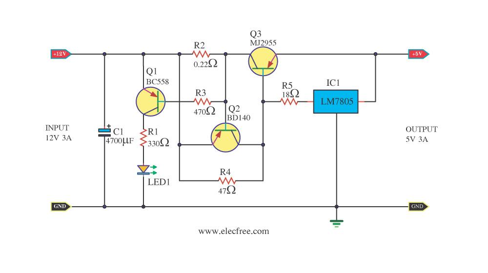
Today, a 12V to 5V 3A DC converter step-down regulator circuit has been presented. Sometimes, individuals have a 12V 3A power supply but require a 5V 3A output for digital circuits. This circuit fulfills that requirement by utilizing standard...
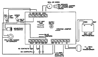
The following alarm circuit is designed with features that may be suitable for residential and commercial alarm system applications. This residential alarm circuit also includes a delay circuit, a 24-hour panic circuit, a built-in siren driver, alarm memory, remote...
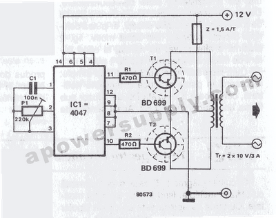
The inverter circuit features the CMOS 4047 as its primary component, converting a 12V DC voltage to a 220V AC voltage. The 4047 operates as an astable multivibrator. A symmetrical rectangular signal is generated at pins 10 and 11,...
Switching to alternative power sources can help reduce electricity bills. The photovoltaic module or solar panel described here is capable of generating renewable energy. The photovoltaic module, commonly known as a solar panel, is a device that converts sunlight into...
This project utilizes common electronic components to create a mobile battery charger using AA cells. The primary component of the circuit is the NE555 timer IC, which is responsible for charging and monitoring the voltage level. The control voltage...
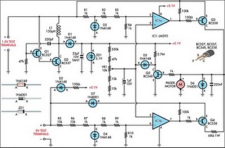
Improved Vibrating Battery Tester. This circuit is based on the LM393 integrated circuit. Features include the ability to test AAA, AA, C, and D cells. The Improved Vibrating Battery Tester utilizes the LM393, a dual comparator IC, to accurately assess...