
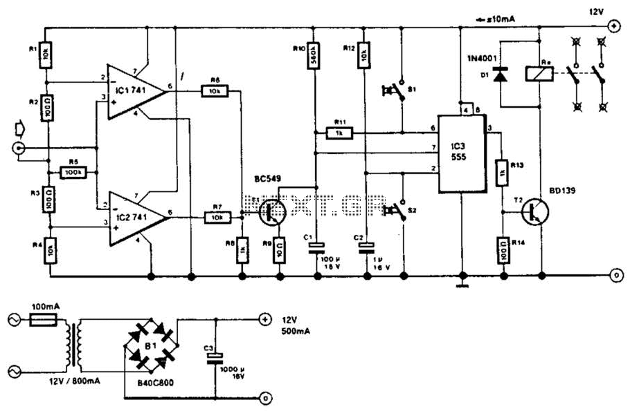
Automatic generator start battery monitor circuit diagram

The generator start battery automatic monitor circuit is designed to oversee the battery's status during generator operation. This circuit ensures that the battery remains charged and functional, preventing premature failure and ensuring reliable generator performance.
The circuit typically includes a battery voltage sensing mechanism, which continuously monitors the battery voltage levels. A microcontroller or comparator may be employed to assess whether the voltage is above or below a predefined threshold. If the voltage falls below this threshold, indicating a low battery condition, the circuit can trigger an alarm or an indicator light to alert the user.
Additionally, the circuit may incorporate a relay or a solid-state switch that can disconnect the battery from the load to prevent deep discharge, which can damage the battery. In some designs, a charging circuit can be integrated to automatically recharge the battery when it is detected to be below the optimal voltage level.
The schematic representation of this circuit would typically include components such as resistors, capacitors, diodes, and transistors, along with the microcontroller or comparator. Proper placement and connection of these components are crucial for the circuit's functionality, ensuring that signals are processed accurately and that the battery is effectively monitored and maintained.
Overall, the generator start battery automatic monitor circuit is an essential component for maintaining battery health and ensuring the reliable operation of generator systems. As shown in FIG generator start battery automatic monitor circuit diagram
Related Circuits
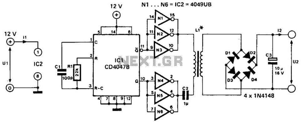
This low-power converter supplies approximately 100 mW of DC power to a load and is useful for isolating or deriving DC voltages. It operates at a frequency of around 200 kHz. The inductor is wound on a 22-mm diameter,...
A USBI2C can be utilized with each sensor, allowing for a configuration of four sensors at a cost of £120. The SRF02 operates on the I2C bus, which should not be extended beyond approximately 2 meters. The proposed solution...
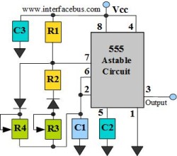
The astable multivibrator circuit lacks a stable state. In the absence of an external signal, the internal transistors alternately switch between cutoff and saturation at a frequency determined by the RC time constants of the coupling circuits. Therefore, an...
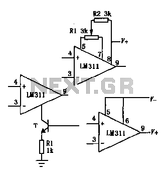
The LM111/211/311 power supply operates within a voltage range of 5V to 15V. It features bias current, offset current, and a differential input voltage range of 30V. The output is compatible with TTL, DTL, and MOS circuits, allowing it...
This circuit will disconnect the line supply to audio or video equipment if there has been no input signal for approximately 2 seconds. Switch SI provides manual operation, while switch S2 functions as a reset mechanism. This circuit allows...
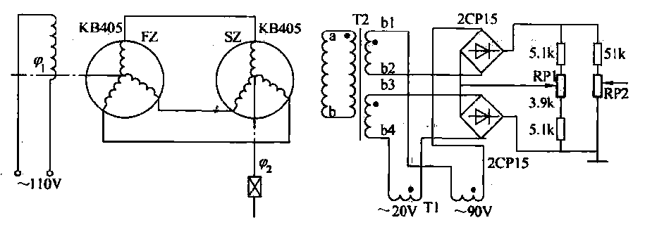
The transmitter (FZ) winding and receiver (SZ) correspond to the three-phase windings connected to a 110V AC voltage supply for transmission. The field winding, early start angle, and receiver output voltage at both ends of the stator windings reflect...