
Automatic Light Controller Using 7806

To derive the power supply for the circuit, a 50Hz, 230V AC mains is stepped down by transformer X1 to deliver a secondary output of 12V at 250 mA. The secondary output of the transformer is applied to a bridge rectifier composed of diodes D1 through D4, filtered by capacitor C1, and fed to the input terminal of the regulator (IC1). The common terminal (pin 2) of IC1 is connected to the ground line of the circuit through transistor BC557 (T1). The transistor is biased by resistors R2, R3, VR1, and LDR1. The grounding of IC1 is controlled by transistor T1, while LDR1 senses light levels. Using preset VR1, the light-sensing level of transistor T1 can be adjusted. The output of IC1 is fed to the base of transistor T2 (through resistor R4 and zener diode ZD1) and relay RL1. LED1, connected across the positive and ground supply lines, serves as a power-on indicator.
Typically, the resistance of LDR1 is low during the daytime and high at nighttime. During the day, when light falls on LDR1, the PNP transistor T1 conducts, connecting the common terminal of IC1 to ground, resulting in an output of 6V from IC1. Consequently, transistor T2 does not conduct, and the relay remains de-energized, keeping the light bulb off as the mains connection is not completed through the relay contacts. At nighttime, when no light falls on LDR1, it presents high resistance at the base junction of transistor T1, significantly reducing the bias and preventing T1 from conducting. This effectively removes the common terminal of IC1 from ground, directing the full input DC to the output. Transistor T2 conducts, energizing the relay to turn on the bulb as the mains connection is completed through the relay contacts.
Since LDR1 is in parallel with the R3 and VR1 combination, it effectively applies only half of the total resistance of the network formed by R3, VR1, and LDR1 to the junction at T1 in total darkness. In bright light, it significantly reduces the total effective resistance at the junction. The circuit is straightforward and can be assembled on a small general-purpose PCB. A heat sink should be used for IC1, and it is essential to ensure that LDR1 and the light bulb are well separated. This circuit can be applied to streetlights, tube lights, or any other home electrical lighting system requiring automation.Voltage regulator ICs (78xx series) provide a steady output voltage, as against a widely fluctuating input supply, when the common terminal is grounded. Any voltage about zero volt (ground) connected in the common terminal is added to the output voltage.
That means the increase in the common terminal voltage is reflected at the output. On the othe r hand, if the common terminal is disconnected from the ground, the full input voltage is available at the output. This characteristic is utilised in the present circuit. When the common terminal is connected to the ground, the regulator output is equivalent to the rated voltage, and as soon as the terminal is disconnected from the ground, the output increases up to the input voltage.
The common terminal is controlled by a transistor, which works as a switch on the terminal. For automatic control of light, a light-dependent resistor (LDR1) is connected to the base of the transistor. In this way, the voltage regulator is able to operate a light bulb automatically as per the ambient light.
To derive the power supply for the circuit, the 50Hz, 230V AC mains is stepped down by transformer X1 to deliver a secondary output of 12V, 250 mA. The secondary output of the transformer is applied to a bridge rectifier comprising diodes D1 through D4, filtered by capacitor C1 and fed to the input terminal of the regulator (IC1).
The common terminal (pin 2) of IC1 is connected to the ground line of the circuit through transistor BC557 (T1). The transistor is biased by R2, R3, VR1 and LDR1. The grounding of IC1 is controlled by transistor T1, while light is sensed by LDR1. Using preset VR1, you can adjust the light-sensing level of transistor T1. The output of IC1 is fed to the base of transistor T2 (through resistor R4 and zener diode ZD1) and relay RL1.
LED1 connected across the positive and ground supply lines acts as a power-on` indicator. Normally, the resistance of LDR1 is low during daytime and high during nighttime. During daytime, when light falls on LDR1, pnp transistor T1 conducts. The common terminal of IC1 connects to the ground and IC1 outputs 6V. As a result, transistor T2 does not conduct and the relay remains de-energised. The light bulb remains off` as the mains connection is not completed through the relay contacts. During nighttime, when no light falls on LDR1, it offers a high resistance at the base junction of transistor T1. So the bias is greatly reduced and T1 doesn`t conduct. Effectively, this removes the common terminal of IC1 from ground and it directs the full input DC to the output.
Transistor T2 conducts and the relay energises to light up the bulb as mains connection completes through the relay contacts. As LDR1 is in parallel to VR1 R3 combination, it effectively applies only half of the total resistance of the network formed by R3, VR1 and LDR1 to the junction at T1 in total darkness.
In bright light, it greatly reduces the total effective resistance at the junction. The circui t is simple and can be assembled on a small general-purpose PCB. Use a heat-sink for IC1. Make sure that LDR1 and the light bulb are well separated. The circuit can be used for streetlights, tubelights or any other home electrical lighting system that needs to be automated. 🔗 External reference
Related Circuits
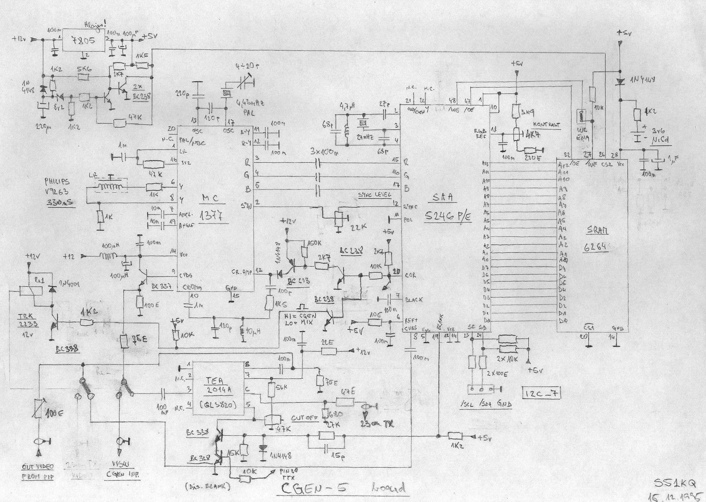
This is an image Schematic. No Description available. The provided input indicates that there is an image schematic without any accompanying description. In scenarios where a schematic is presented, it typically contains graphical representations of electronic components and their...
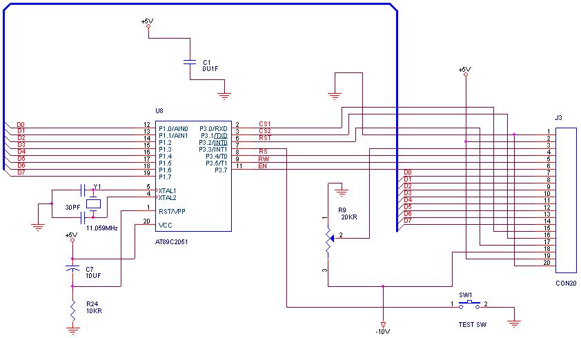
How can graphical LCDs be controlled using a microcontroller? Is there any datasheet available? Graphical LCDs (Liquid Crystal Displays) are widely used in various electronic applications for displaying complex graphics and text. To control these displays with a microcontroller, several...
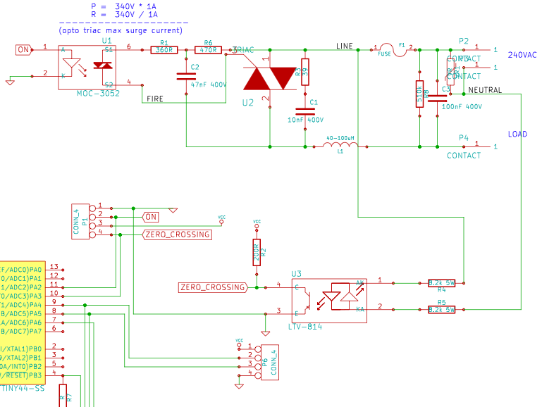
The resistance of the heater is constructed using 9 Ω nichrome wire with a diameter of 3 mm. When supplied with 240V (rms) voltage, this configuration results in a current of 25A (rms). Access to a mains line that...

This document discusses the use of small microcontrollers, such as those from the PIC and Atmel series, which typically operate at 5V and require less than 100mA for complete system functionality. Some PICs can function at lower voltages, such...

The circuit utilizes the Trigger and Threshold pins (2 and 6) to monitor maximum and minimum voltage levels. Two voltage comparator operational amplifiers within the 555 timer manage the output state, switching it on or off. The Trigger pin...
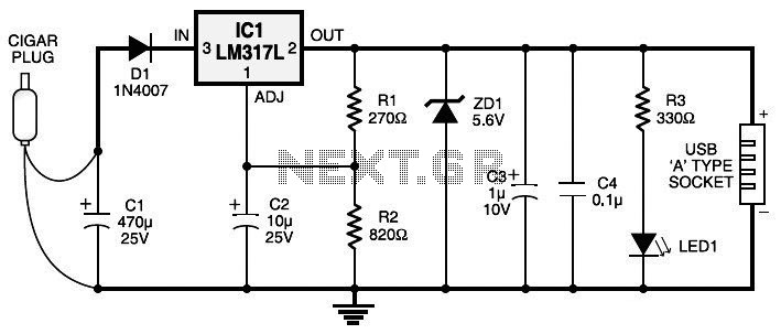
Currently, nearly all computer systems include logic blocks designed for interfacing with a USB port. In practical terms, a USB port can provide more than 100 mA of continuous electric current at 5V to the peripherals connected to the...