
automatic room light controller with

This circuit serves as a practical solution for automating room lighting based on occupancy, utilizing a combination of infrared sensing technology and microcontroller programming. The IR transmitter continuously emits a modulated signal, which the TSOP1738 sensor detects. When a person enters the room, the interruption in the IR signal triggers the microcontroller to increment the count of individuals present. The display provides a visual representation of the count, allowing for easy monitoring. The relay control mechanism ensures that the lighting operates only when necessary, contributing to energy efficiency. The monostable multivibrator configuration within the IC555 allows for precise timing control, ensuring that the system remains responsive to changes in occupancy while maintaining a defined delay for stability. The reset functionality enables the system to be cleared and restarted as needed, enhancing usability and flexibility in various environments. Overall, this project exemplifies the integration of simple electronic components into a cohesive system that addresses everyday needs through automation.The objective of this project is to make a controller based model to count number of persons visiting particular room and accordingly light up the room. Here we can use sensor and can know present number of persons. In today`s world, there is a continuous need for automatic appliances with the increase in standard of living, there is a sense of ur
gency for developing circuits that would ease the complexity of life. The IR transmitter will emit modulated 38 kHz IR signal and at the receiver we use TSOP1738 (Infrared Sensor). The output goes high when the there is an interruption and it return back to low after the time period determined by the capacitor and resistor in the circuit.
I. e. around 1 second. CL100 is to trigger the IC555 which is configured as monostable multivibrator. Input is given to the Port 1 of the microcontroller. Port 0 is used for the 7-Segment display purpose. Port 2 is used for the Relay Turn On and Turn off Purpose. LTS 542 (Common Anode) is used for 7-Segment display. And that time Relay will get Voltage and triggered so light will get voltage and it will turn on. And when counter will be 00 that time Relay will be turned off. Reset button will reset the microcontroller. Microcontroller based Visitor Counter. This circuit diagram shows how a 555 timer IC is configured to function as a basic monostable multivibrator. A monostable multivibrator is a timing circuit that changes state once triggered, but returns to its original state after a certain time delay.
It got its name from the fact that only one of its output states is stable. It is also known as a `one-shot`. In this circuit, a negative pulse applied at pin 2 triggers an internal flip-flop that turns off pin 7`s discharge transistor, allowing C1 to charge up through R1. At the same time, the flip-flop brings the output (pin 3) level to `high`. When capacitor C1 as charged up to about 2/3 Vcc, the flip-flop is triggered once again, this time making the pin 3 output `low` and turning on pin 7`s discharge transistor, which discharges C1 to ground.
This circuit, in effect, produces a pulse at pin 3 whose width t is just the product of R1 and C1, i. e. , t=R1C1. IR Transmission circuit is used to generate the modulated 36 kHz IR signal. The IC555 in the transmitter side is to generate 36 kHz square wave. Adjust the preset in the transmitter to get a 38 kHz signal at the o/p. around 1. 4K we get a 38 kHz signal. Then you point it over the sensor and its o/p will go low when it senses the IR signal of 38 kHz. 🔗 External reference
Related Circuits
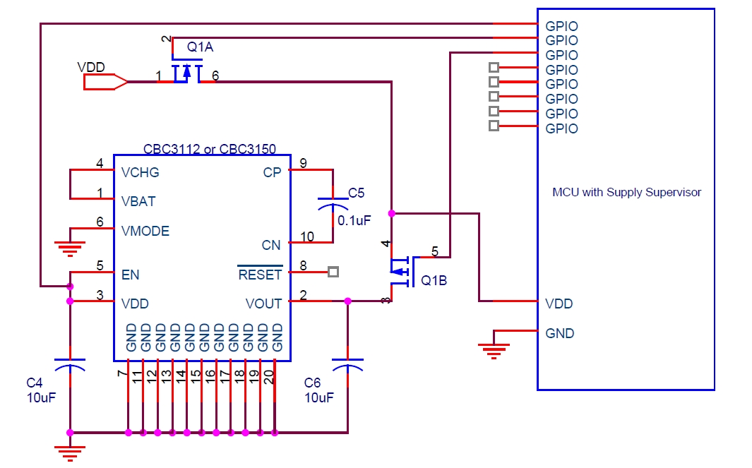
Cymbet Corporation provides rechargeable solid-state batteries designed for advanced microcontroller power backup applications. The company is recognized as a leader in thin-film energy storage technology. Cymbet Corporation's rechargeable solid-state batteries are engineered to deliver reliable power solutions for microcontrollers, which...

Voltage regulator ICs (78xx series) provide a steady output voltage, in contrast to a widely fluctuating input supply, when the common terminal is grounded. The 78xx series of voltage regulator integrated circuits (ICs) are widely utilized in electronic circuits to...
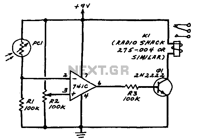
R2 sets the circuit's threshold. When the light intensity at the PCI's surface decreases, the resistance of PCI, a cadmium-sulfide photo-resistor, increases. This results in a decrease in voltage at the inverting input of the 741 operational amplifier. When...
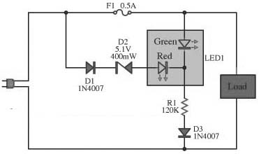
This circuit is designed to monitor the performance of the equipment. It includes a fuse check feature. The circuit is compact and can operate with various power supply voltages. It utilizes a two-color LED, which is of the common...
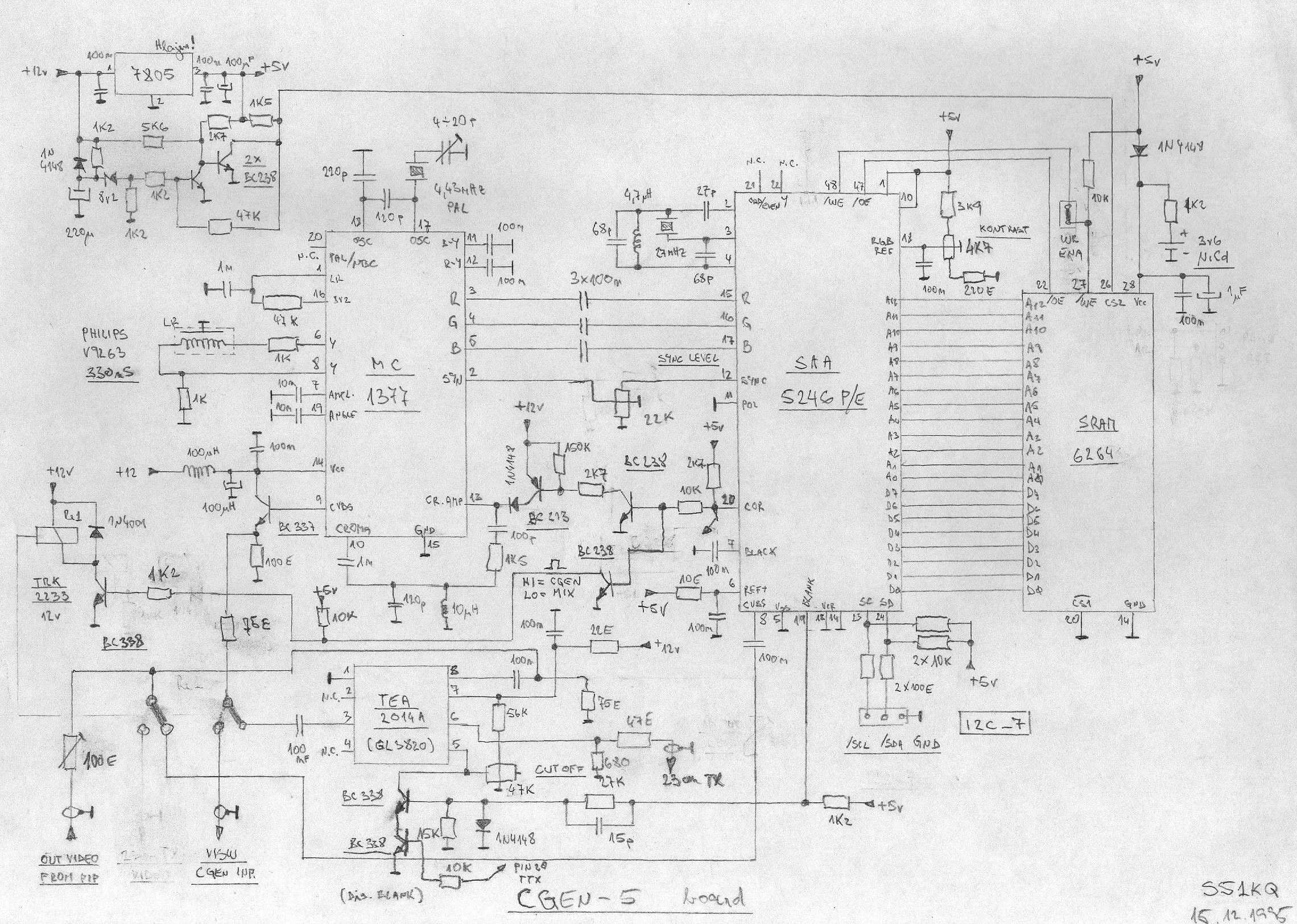
This is an image Schematic. No Description available. The provided input indicates that there is an image schematic without any accompanying description. In scenarios where a schematic is presented, it typically contains graphical representations of electronic components and their...
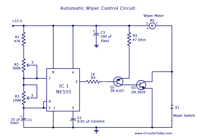
A circuit for car windshield/wiper motor speed control built using an NE 555 IC. This enables intermittent windshield wiper control, which changes the sweep rate to 10 seconds. The circuit utilizes the NE 555 timer IC configured in astable mode...