
Automatic Tr Switch Circuit

The circuit design employs two diodes, D1 and D2, configured in a manner that allows them to operate effectively as a transmit-receive (TR) switch. During the transmit phase, both diodes are forward-biased, creating a low-resistance path that short-circuits the scanner input. This configuration prevents any incoming signals from interfering with the transmission process. The quarter-wave transmission line plays a critical role in this setup. When active, it behaves as an open circuit, effectively isolating the scanner input from the output during transmission.
In the receive mode, the circuit transitions to operate as a Wilkinson power divider. This is achieved by the inherent properties of the quarter-wave transmission line, which allows for the division of power between multiple outputs without introducing significant loss. The Wilkinson power divider is known for its ability to maintain impedance matching, ensuring that reflections are minimized and the power is efficiently distributed among the outputs. This dual functionality of the circuit allows for seamless switching between transmitting and receiving modes, making it suitable for applications in communication systems where rapid transitions between states are necessary.
The design must ensure that the diodes are selected based on their switching speed and reverse recovery time to minimize any delay during the transition between transmit and receive modes. Additionally, careful consideration of the quarter-wave line's characteristic impedance is crucial to maintain the desired performance in both operational states. Overall, this circuit exemplifies a compact and efficient solution for automatic TR switching in RF applications. A pair of diodes and a quarter-wave transmission line are used as an automatic TR switch. D1 and D2 conduct during transmit periods, short- circuiting the scanner input. In this mode,-the K-wave line appears as an open circuit. In receive, the circuit acts as a Wilkinson power divider.
Related Circuits
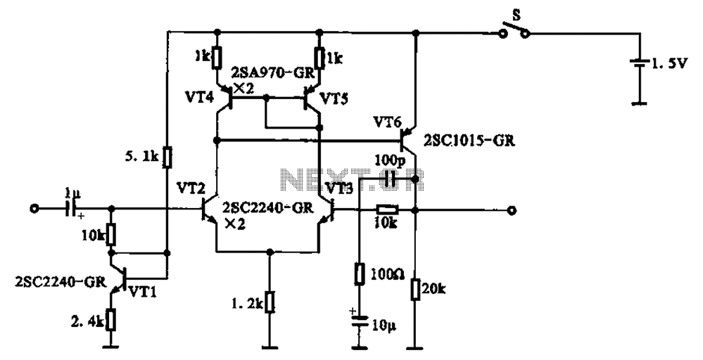
A 1.5V-powered microphone signal amplifying circuit is designed with a power supply for the microphone signal amplification. The circuit primarily consists of a differential amplifier formed by transistors VT2 and VT3. Additionally, VT6 functions as a common emitter voltage...
This electronic timer switch will turn on a light for 100 seconds, turn it off for another 100 seconds, and then turn it on again for 100 seconds after an hour of powering up the circuit. It is a...
S1 and S2 are normally open, push-to-close, momentary switches. The diodes, which can be either red or green, serve solely to indicate the direction of operation. The TIP31 transistors may need to be adjusted based on the specifications of...
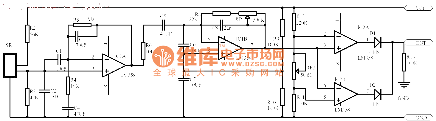
Passive human body infrared sensor circuits are generally similar in design, although some may have fewer stages. The circuit illustrated is sourced from the NICERA manufacturer and is considered a classic example. The front-end stage consists of a low-frequency...
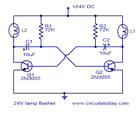
The circuit operates on 24V DC and is designed to alternately flash two 24V bulbs. It functions as an astable multivibrator with a frequency of 1Hz and a duty cycle of 50%. The lamps to be flashed are connected...
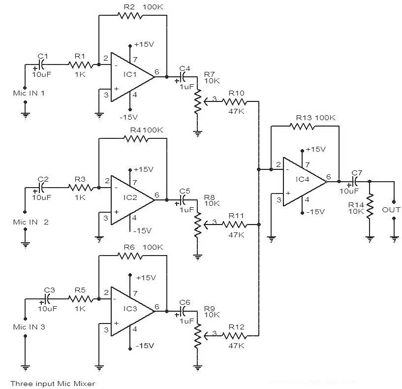
This is a circuit diagram of a 741 IC-based three-input microphone mixer circuit. A total of four 741 ICs are utilized, with IC1, IC2, and IC3 serving specific functions within the design. The circuit utilizes four operational amplifiers from the...