
Automatic-video-switch
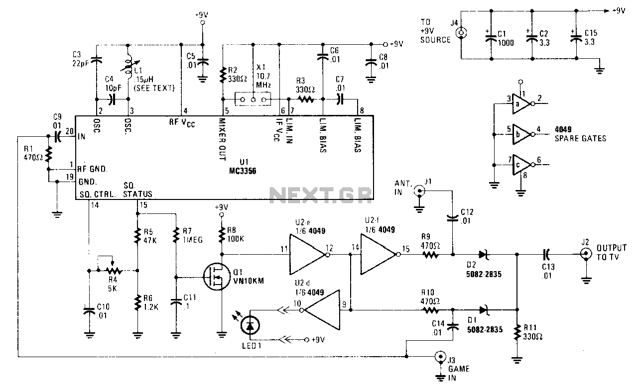
Turn on a game console, computer, videodisc player, or any similar device, and its output takes precedence over the antenna-derived signal. The antenna is disconnected, and the alternate source is fed to the monitor. When the alternate video source is no longer detected, the switch automatically reconnects the antenna. When the RF carrier is detected, a high logic output appears at pin 15 of U1, indicating squelch status. The signal is then buffered to VMOS FET Q1. This FET can drive a CMOS inverter/buffer U2, serve as an open-drain output to drive a relay, or convert to a 5V logic level. When pin 15 of U1 becomes high, Q1 turns on, pulling pin 11 of U2e low; in turn, pin 12 becomes high. The output of U2e is fed to U2f, forcing its output at pin 15 low. When the signal at U2 pin 12 is high, it is biased on, allowing the signal at J3 to flow through C14, D1, and out to J2 through C13. When the signal at J3 is removed, U1 pin 15 decreases. This decrease causes U2 pin 12 to decrease and U2 pin 15 to increase. When the signal at U2 pin 15 is high, it biases D2 on, allowing the signals at J1 to flow through C12, D2, and out to J2 through C13.
The circuit described operates as a switching mechanism for video sources, ensuring that the output from devices such as game consoles or computers takes priority over signals received from an antenna. The system utilizes a squelch status indication, which is critical for determining the presence of an RF carrier signal.
The primary component, U1, monitors the input signals and generates a high logic output at pin 15 when an RF carrier is detected. This output is crucial for controlling the state of Q1, a VMOS FET that acts as a switch. When Q1 is activated, it pulls pin 11 of U2e low, which in turn causes pin 12 of U2e to go high. This logic state change propagates through U2f, affecting its output at pin 15, which is subsequently pulled low.
The interaction between U2e and U2f creates a feedback loop that ensures the correct signal routing based on the presence of the alternate video source. Capacitors C14 and C13, along with diodes D1 and D2, are employed to manage signal flow and ensure proper biasing conditions for the respective components. The circuit design allows for seamless switching back to the antenna-derived signal when the alternate source is no longer available, maintaining functionality without manual intervention.
Overall, the combination of these components ensures an efficient and automatic switching mechanism that enhances user experience by prioritizing preferred video sources while maintaining the capability to revert to antenna signals as needed. The design exemplifies effective use of logic control, signal buffering, and switching techniques in electronic circuit design.Tum on a game, computer, videodisc player, or whatever, and its output takes priority over the antenna-derived signal-the antenna is disconnected and the alternate source is fed to the monitor. When the alternate video source is no longer detected, the switch automatically reconnects the antenna.
When the rf carrier is detected, a high logic output appears at pin 15 of U1-squelch status. The signal is then buffered to VMOS FET Ql. This FET can drive CMOS inverter/buffer U2, can be an open-drain output to drive a relay, or can convert to a 5 V logic level. When pin 15 of U1 becomes high, Q1 turns on, pulling pin 11 of U2e low; in tum, pin 12 becomes high. The olitput of U2e is fed to U2f, forcing its output, at pin 15, low. When the signal at U2 pin12 is high, in is biased on, allowing the signal at]3 to flow through C14, D1, and out to ]2 through C13.
When the signal at ]3 is removed, U1 pin 15 decreases. That decrease causes U2 pin 12 to decrease and U2 pin 15 to increase. When the signal at U2 pin 15 is high, it biases D2 on, allowing the signals at Jl to flow through Cl2, D2, and out to ]2 through Cl3. 🔗 External reference