Motor speed control
#motor speed control
#DC motor
#LM3524
#LM2907
#speed sensor
#regulating circuit
#drive circuit
#PWM control
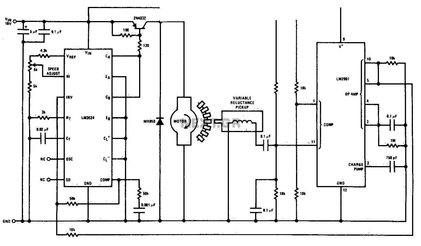
Description: This circuit is a regulating series DC motor speed control using the LM3524 for the control and drive of the motor and the LM2907 as a speed sensor for the feedback network.
The circuit employs the LM3524 integrated circuit, which serves as both a controller and driver for the DC motor. The LM3524 is a versatile PWM (Pulse Width Modulation) controller that can be utilized to regulate the speed of a DC motor by varying the duty cycle of the output signal. The output from the LM3524 drives a power transistor or MOSFET that controls the voltage supplied to the motor, thus enabling speed regulation.
The LM2907 is used as a speed sensor, providing feedback on the motor's rotational speed. The LM2907 operates as a frequency-to-voltage converter, translating the frequency of the motor's rotation into a proportional voltage. This feedback voltage is then fed back to the LM3524, allowing for closed-loop control of the motor speed. The feedback mechanism ensures that the motor speed can be adjusted dynamically based on the load conditions and desired speed setpoint.
In the schematic, the LM3524 is configured with necessary external components, including resistors and capacitors, to set the PWM frequency and to stabilize the control loop. The use of an appropriate power transistor or MOSFET is crucial for handling the motor's current requirements. The LM2907 is connected to the motor shaft, typically through a gear or a tachometer, to accurately sense the speed of the motor.
Overall, this circuit design provides an effective solution for controlling the speed of a DC motor with high precision and responsiveness, making it suitable for various applications in automation and robotics.This circuit is a regulating series dc motor speed control using the LM3524 for the control and drive for the motor and the LM2907 as a speed sensor for the feedback network.
