
Backup Power System with PIC16F870

In order to measure currents up to 10 amps, 0.01 ohm resistors were made out of about 5 inches of #22 solid hookup wire. A simple resistor divider is used to monitor the voltage.
Since this is a Pulsed charging system (note lack of humongous filter capacitors), the battery voltage is only measured between the charge pulses. The AC connection to RC1 is used to synchronize this operation. Also, making a reasonable current measurement is done by summing several samples spaced over one complete charge pulse interval. In other words, the actual charge is going on only about 20 percent of the time. So taking samples over the entire interval automatically 'does the math'.
The circuit employs a PIC16F870 microcontroller, which serves as the central processing unit for monitoring battery conditions and controlling the associated relay systems. The microcontroller interfaces with a 4-digit display to present real-time battery voltage and current readings, ensuring user visibility of the system's operational status. The design incorporates a load relay that connects to a 12V DC system, which powers various devices such as lights and fans when the AC power source is unavailable.
To prevent battery damage, the system continuously monitors the battery voltage. If the voltage drops below a predetermined threshold, the load relay is disengaged to protect the batteries from over-discharging. The monitoring of charging and discharging currents is achieved through precision resistors (0.01 ohms) made from #22 solid hookup wire, which allows for accurate current sensing up to 10 amps. The voltage across these resistors is measured using a resistor divider network, providing proportional voltage levels suitable for the microcontroller's analog input.
The charging system operates in a pulsed mode, which is characterized by the absence of large filter capacitors typically found in linear power supplies. Instead, the battery voltage is sampled only during charge pulses, with synchronization provided by the AC connection to RC1. This sampling strategy allows for efficient measurement of battery conditions, as the actual charging occurs for approximately 20% of the time, enabling the system to calculate average current over the entire pulse interval.
The redesign of the power management system involved the removal of an SCR previously used for switching power from the rectifiers to the battery. This was replaced with a solid-state relay positioned in the primary circuit of the transformer, which significantly reduces idle current draw. The configuration enhances overall efficiency while maintaining reliable operation of the battery management system.The PIC16F870 keeps track of battery voltage as well as both charging and discharging currents. It also drives the 4 digit display, and switches the AC and load relays. The basic operation is as follows: While AC power is available, the battery voltage is constantly monitored and topped off as needed. When the AC power fails, the load relay engages the 12-volt system. This connects to lights, fans, and other 12 volt devices as needed. Should the battery voltage fall too low, the load relay is disengaged, preventing the acid batteries from being damaged by over discharging.
Refering to the SCHEMATIC, which differs some from the LAYOUT, the planned SCR that switched power from the power rectifiers to the battery was eliminated from the design. (This left a redunant diode feeding power to the 7805). Instead, a 110 volt solid-state relay was added to the transformer primary circuit. This eliminated the rather large idling current from the scrounged transformer. In order to measure currents up to 10 amps, .01 ohm resistors were made out of about 5 inches of #22 solid hookup wire.
A simple resistor devider is used to monitor the voltage. Since this is a Pulsed charging system (note lack of humongus filter capacitors), the battery voltage is only measured between the charge pulses. The ac connection to RC1 is used to synchronize this operation. Also, makeing a reasonable current measurement is done by summing several samples spaced over one complete charge pulse interval.
In other words, the actual charge is going on only about 20 percent of the time. So taking samples over the entire interval automatically 'does the math'. 🔗 External reference
Related Circuits
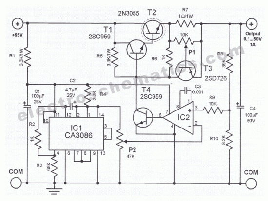
0.1V to 50V Variable Power Supply Circuit Diagram. Features: the lowest current limit is 0.6 ampere, opamp CA3130 compares the reference voltage. The variable power supply circuit is designed to provide an adjustable output voltage ranging from 0.1V to 50V,...
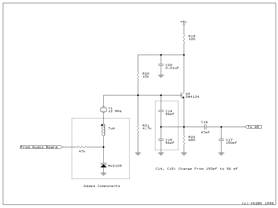
A model RTX-70 exciter was originally utilized in the Brookdale ATV Repeater System. This document outlines the design considerations and new features of this exciter, including schematics of the circuits developed during its creation. The ATV exciter described employs...
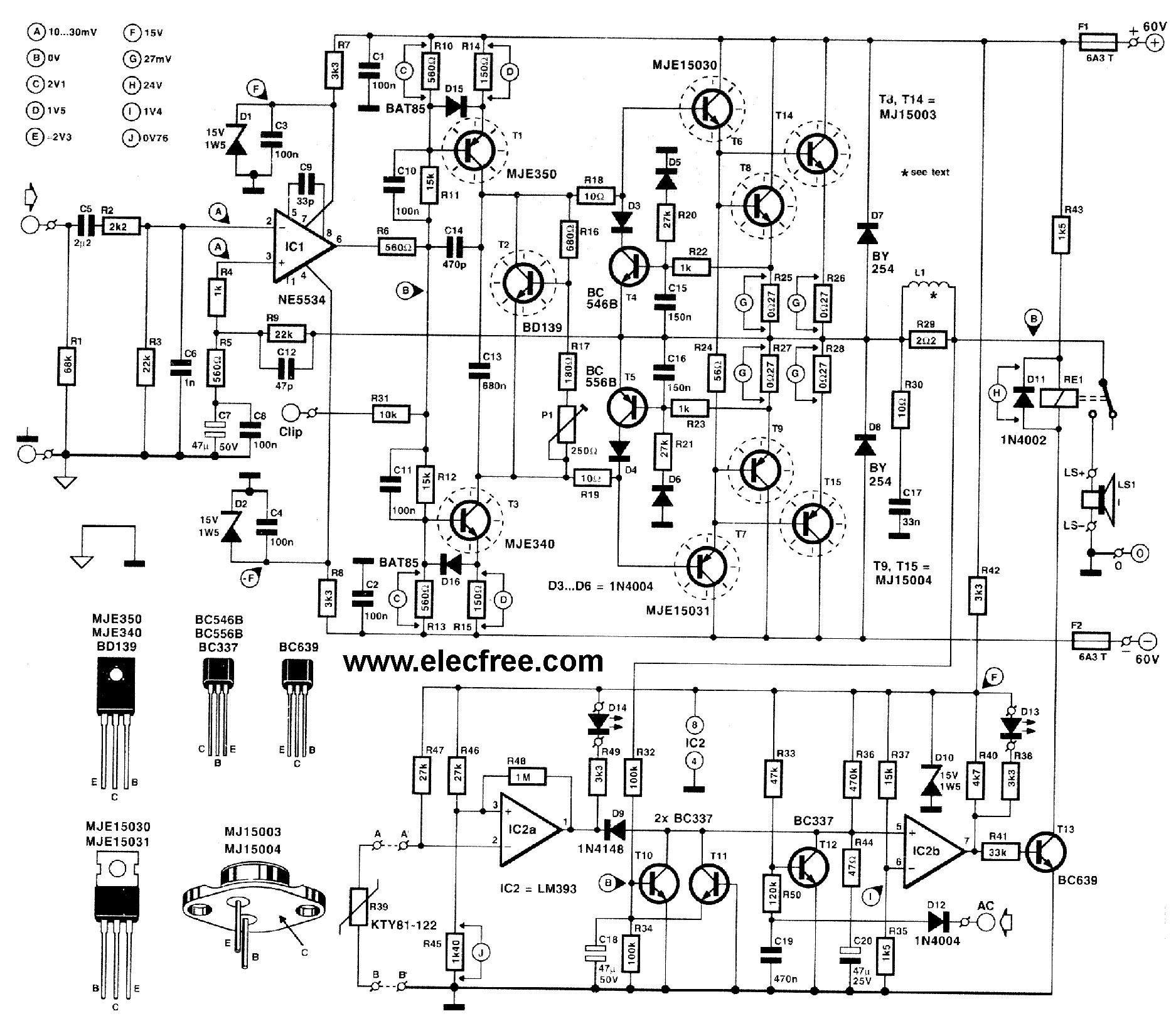
This circuit is designed for friends who are interested in high-power amplifier circuits. It can deliver approximately 300 Watts RMS and operates as an OCL (Output Capacitor-Less) Class AB amplifier, providing high sound power while systematically protecting the loudspeaker...
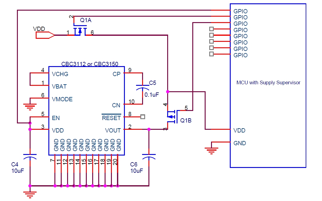
Cymbet Corporation provides rechargeable solid-state batteries designed for advanced microcontroller power backup applications. The company is recognized as a leader in thin-film energy storage technology. Cymbet Corporation's rechargeable solid-state batteries are engineered to deliver reliable power solutions for microcontrollers, which...
The APX9132 integrated circuit is an ultra-sensitive, pole-independent Hall-effect switch featuring a latched digital output. It operates within a voltage range of 2.5 volts to 3.5 volts, and its unique clocking scheme reduces average power consumption. The output activates...
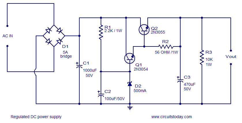
A low ripple regulated DC power supply designed using transistors is presented. These transistor voltage regulators are suitable for applications requiring high output current. Conventional integrated series regulators, such as the 7805, can only deliver up to 1A. To...