
Basic Microphone preamplifier

This preamplifier circuit is designed to amplify low-level audio signals from microphones, enabling further processing or amplification stages. The circuit utilizes two transistors, specifically the BC549C and BC547B, which are common choices for audio applications due to their low noise characteristics and high gain.
The circuit configuration typically consists of a differential amplifier stage formed by the two transistors, which helps to minimize noise and enhance the signal-to-noise ratio. The input impedance is critical for microphone compatibility, and in this design, it is suitable for microphones with an impedance ranging from 500 to 600 ohms. Resistor R1, typically set at 470 ohms, may be adjusted to 220 ohms for specific microphone types to optimize performance.
Capacitor C1, initially suggested as 2.2 µF, can be increased to 4.7 µF to improve low-frequency response and coupling, ensuring that the audio signal passes through without significant attenuation. The gain of the amplifier is primarily determined by resistor R2, which is set to 22 kOhms for a maximum gain of approximately 200 times. This high gain is essential for amplifying weak signals from microphones to a level suitable for further processing.
Additional resistors (R3 to R8) are included to stabilize the circuit, set biasing conditions, and control the gain across different operating conditions. Capacitors C2 and C3 serve to filter out unwanted noise and stabilize the power supply, while C4 provides additional coupling and decoupling capabilities.
This preamplifier circuit is an effective solution for audio applications, ensuring that microphone signals are amplified with minimal noise and distortion, making it suitable for various audio processing tasks.This preamplifier amplifies the signal from a microphone, an amplifier so that it can be further strengthened. The circuit supplies an output signal line. With two transistors, it is not difficult to build such a circuit. The amplifier produces noise Weining. In the drawn embodiment the circuit suitable for microphones from 500 to 600 ?. R1 200 ? for microphones should be reduces to 220 ? and C1 should be increased to 4.7 uF. The gain is set by R2. If the average declared value of 22 kOhm used. The maximum gain is about 200 times. Parts List R1 = 470 ? R2 = 22 kOhm R3 = 12 kOhm R4 = 47 kOhm R5 = 820 ? R6 = 100 ? R7 = 1 kOhm R8 = 100 kOhm C1, C4 = 2.2 V ?F/16 C2 = 47 V ?F/16 C3 = 470 nF T1 = BC 549C T2 = BC 547B 🔗 External reference
Related Circuits
Although many album titles that were once available on vinyl are gradually being released as CDs, not all are accessible. There may be valuable records in a collection that one wishes to convert to CDs. Preserving a CD is...
AM radio receivers demodulate amplitude-modulated (AM) signals. The primary source of these signals is the Standard AM Radio Broadcast Band, although shortwave stations also utilize AM modulation. Amplitude modulation was developed between 1900 and 1917 by amateur radio enthusiasts....
Design and dimensioning of active low-pass and high-pass filters using Sallen-Key and multiple feedback topologies. Spice netlist generator. Active low-pass and high-pass filters are essential components in signal processing, allowing specific frequency ranges to pass while attenuating others. The Sallen-Key...
To complement the 60 Watt MOSFET Audio Amplifier, a high-quality preamplifier design was necessary. A discrete component topology, utilizing ±24V supply rails, was chosen, maintaining a minimal transistor count while still achieving low noise, very low distortion, and a...
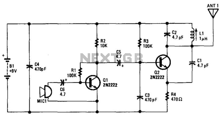
Q1 amplifies the output from an electret microphone (MIC1). The audio signal is fed into oscillator Q2, which modulates the signal. Additionally, L1 and C1 form a tank circuit designed for operation in the 88-MHz frequency range. The antenna...
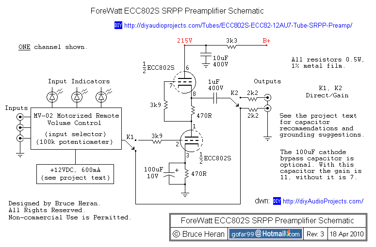
The project involves a shunt-regulated push-pull (SRPP) driver stage. Research and modeling have been conducted on the SRPP, highlighting its advantages, which include good linearity, low distortion, low output impedance, effective power supply noise rejection, and moderate gain. The...