
batteries Li-Poly battery charger with protection Schematic review

The described circuit employs a PMOS transistor to manage the power supply from a USB source while simultaneously protecting the battery from overcharging. The PMOS transistor is strategically placed in the circuit to disconnect the battery from the power supply when USB power is available, thus ensuring that the device operates solely on USB power. This configuration prevents the risk of the battery being charged too rapidly or being subjected to inappropriate voltage levels that could lead to damage.
Resistor R3 plays a crucial role in maintaining the PMOS in an 'on' state when the USB power is absent, which allows the circuit to revert to battery operation seamlessly. This design consideration is critical for devices that rely on battery backup in the absence of external power. The trickle charging mechanism is essential for maintaining battery health, particularly when the battery voltage drops to 2.5V. By slowly increasing the voltage to 3V, the charging circuit ensures that the battery can safely accept higher currents without the risk of thermal runaway or capacity loss.
To address the concern regarding current distribution between the device and the battery, the introduction of a resistor between the battery and the BAT pin of the IC is a viable option. This resistor increases the impedance, effectively limiting the current that can flow to the battery during the charging process. This strategic placement allows the majority of the current to be utilized by the device while still permitting a controlled amount of current to trickle charge the battery. The value of the resistor must be carefully selected to balance the needs of the load and the charging requirements of the battery, ensuring that both components operate efficiently within their specified limits.
Overall, this circuit design demonstrates a thoughtful approach to managing power from a USB source while maintaining battery integrity and functionality. It highlights the importance of component selection and circuit configuration in achieving reliable performance in electronic devices reliant on dual power sources.When USB present and device needs to work, VSupply is directly provided by the USB and PMOS separates the battery from the supply. (R3 ensures PMOS is on when there is no USB) Primary reason for this is not to disturb the proper charging of the battery.
Especially battery is in 2. 5V level, it needs to be trickle charged to 3V and than maximum current can be applied. However without separating the battery from the supply, I couldn`t come up with a way to make this work, hence the PMOS. My circuit takes less than 500mA at any given time however I cannot gurantee how much current can be allocated to the battery.
This is a point I don`t know how to deal with. How do I guarantee the bulk of the current goes to device and remaining used for charging Should I put a resistor between battery and BAT pin of the IC to increase its impedance so that most of the current goes to the load. 🔗 External reference
Related Circuits
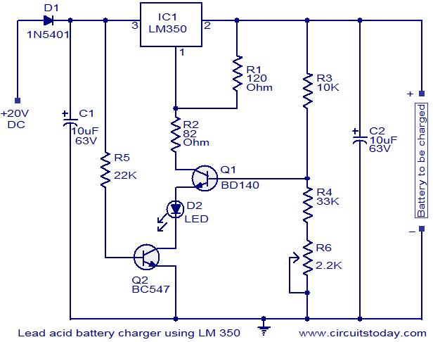
This circuit utilizes the IC LM350 for charging 12V lead-acid batteries, providing a constant voltage source with a negative temperature coefficient. The transistor Q1 (BD140) functions as a temperature sensor, while transistor Q2 prevents the battery from discharging through...
Flyback LED drivers are versatile as they can be utilized in applications with input voltages either above or below the necessary output voltages. They feature a straightforward circuit configuration that maintains a constant LED current without the need for...

The battery should charge up to 14 volts. A reading of 10.7 volts indicates that one cell is shorted. A good way to diagnose this further is to look at the water level in the cells. The shorted cell...

The LMP91200 is a configurable sensor analog front-end (AFE) designed for managing low-power analytical sensing applications, specifically for 2-electrode sensors. This device offers all the necessary functionality to detect changes based on a delta voltage from the sensor. It...

The CMOS 4001 consists of four independent two-input NOR gates. These gates are organized into two pairs. Gates 1 and 2 are connected to form a latching circuit. When the alarm is triggered, they will latch and activate the...
IC1 operates as an oscillator that drives an infrared LED with pulses of 0.8 milliseconds at a frequency of 120 Hz, generating approximately 300 mA of peak current. Diodes D1 and D2 are aligned and positioned a few centimeters...