
BC517 Bipolar Stepper Motor Control

The BC517 bipolar stepper motor control circuit utilizes a BC517 transistor to manage the operation of a bipolar stepper motor. This type of motor is characterized by having two windings, which allows it to operate with positive current flowing through each winding independently. The circuit typically includes a microcontroller or a dedicated stepper motor driver IC that generates the necessary control signals for the transistors.
In this configuration, each winding of the stepper motor is connected to the collector of a BC517 transistor, which acts as a switch. When the microcontroller sends a high signal to the base of the transistor, it allows current to flow from the collector to the emitter, energizing the corresponding winding. By alternating the activation of the two windings, the stepper motor can be made to rotate in precise increments, providing accurate control over its position.
The circuit may also include additional components such as resistors to limit the base current to the transistors and diodes for flyback protection, preventing voltage spikes when the motor is turned off. Properly designed, this circuit enables efficient control of the stepper motor, making it suitable for various applications such as robotics, CNC machines, and other precision motion control systems.BC517 Bipolar Stepper Motor Control Circuit Diagram. Features: Each winding can carry a positive current, A bipolar motor has two windings . 🔗 External reference
Related Circuits
When a key is pressed, the remote control transmits a preamble followed by 32 bits of information encoded using specific pulse timings. The pulse examples can be observed in logic analyzer screen captures, although some glitches are present due...
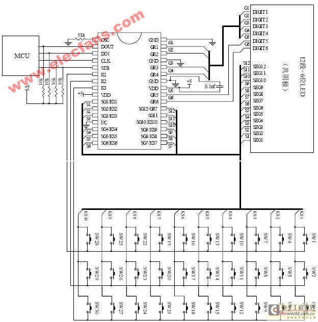
The ET6201 is a LED display control drive circuit with a duty cycle of 1/7 to 1/8. It features 11 segment output gates and 1 segment/gate output, along with a display memory, control circuit, and key scanning circuit, which...
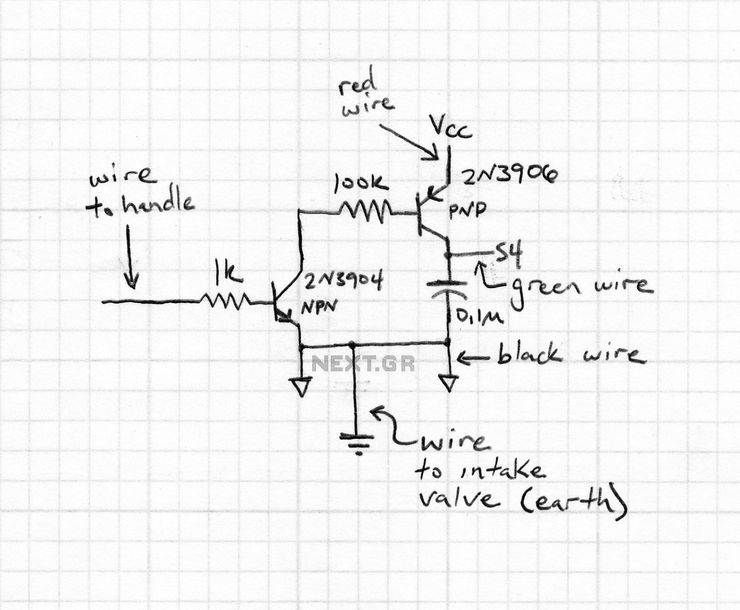
The circuit described here is for a general purpose device that can control DC devices which draw up to a few amps of current. The circuit may be used in either 12 or 24 Volt systems with only a...
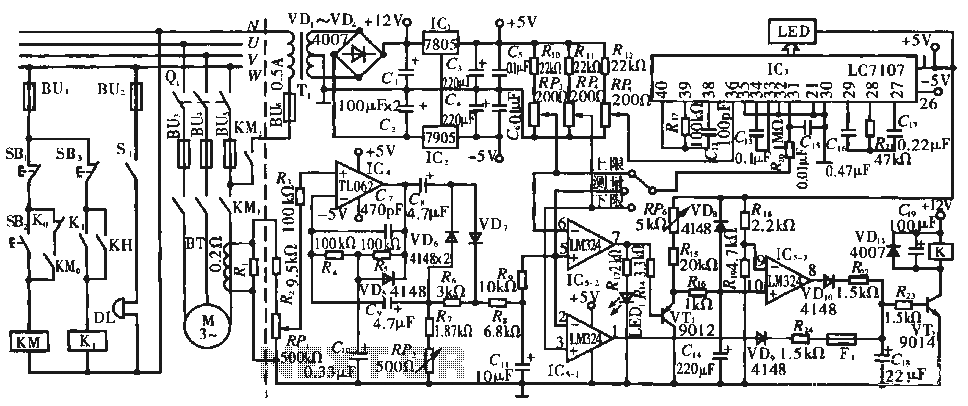
The circuit operates during standard inspection work by utilizing the voltage across resistor R2, which is connected to RP, to generate the input signal for IC4. Components R3 through Rg, along with capacitors C7 and C1, and diodes VD7...
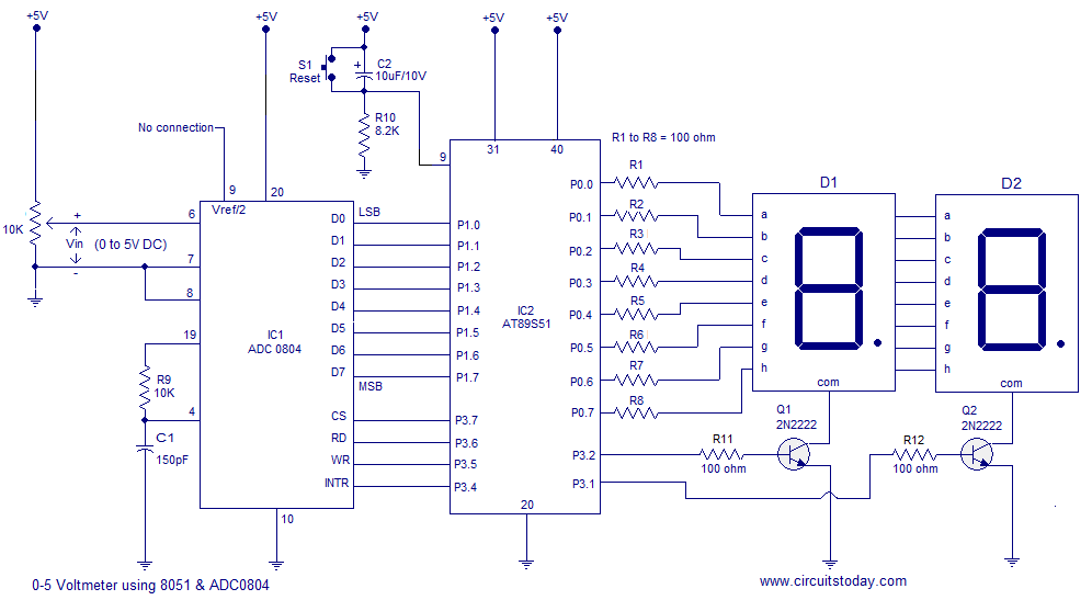
A simple 0-5 digital voltmeter utilizing the 8051 (AT89S51 microcontroller) is presented, accompanied by a circuit diagram and assembly language (ASM) code. This digital voltmeter is designed for straightforward voltage measurement. The circuit employs an AT89S51 microcontroller, which serves as...

Three power levels are provided by the two logic inputs of this enhanced circuit. R5, D4, D5, and O2 create a power supply for the logic integrated circuit. These components can be excluded if an alternative low voltage source...