
Beat-Frequency Audio Generator

The circuit features a fixed oscillator (Q1) that generates a stable frequency of 455 kHz, which is commonly used in RF applications such as AM radio receivers. The mixer (U1) incorporates its own internal oscillator operating at a lower frequency of 45.5 kHz. This configuration allows for frequency mixing, where the two frequencies can interact to produce intermediate frequencies that can be further processed.
The use of Murata CSB455E filters (FIL1 and FIL2) ensures that only the desired frequency components are passed through while attenuating unwanted signals, thereby improving the selectivity of the circuit. The filters are critical in maintaining signal integrity and preventing interference from other frequencies.
The varactor diode (D1), specifically the IN4002 when used in this application, serves to adjust the oscillator frequency. The variable resistor R6 applies a bias voltage to the varactor diode, which alters its capacitance. This change in capacitance directly affects the oscillator frequency, allowing for fine-tuning of the output frequency by a few kHz. This feature is particularly useful for applications requiring precise frequency adjustments.
The audio beat note is extracted from pin 5 of the mixer (U1) through an RF filter (L2) and capacitor (C10). This stage is crucial for isolating the audio signal generated by the mixing process, enabling it to be further processed or amplified for audio output. Overall, this circuit is designed for efficient frequency generation and mixing, with components selected for optimal performance in RF applications. Ql is a fixed oscillator operating at 455 kHz. Ul is a mixer, with its own internal oscillator running at 45 5 kHz. FIL1 and FIL2 are Murata CSB455E filters or equivalent. Dl is a varactor diode (an IN4002 used as a varactor works well here). R6 controls the bias on Dl. When R6 is varied, the oscillator frequency varies a few kHz. Audio beat note is taken, through RF filter L2 and CIO, from pin 5 of Ul.
Related Circuits
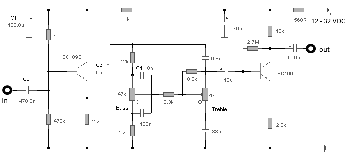
The first BC109C transistor functions as a buffer, offering the circuit an input impedance of approximately 250,000 ohms and a voltage gain just below unity. As the Baxandall tone control circuit is a passive design, it attenuates all audio...
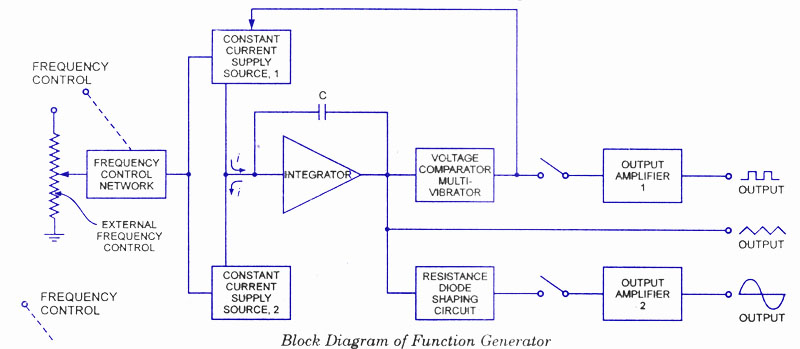
A function generator is a signal source capable of producing various types of waveforms as its output signal. The most common output waveforms include sine waves, triangular waves, square waves, and sawtooth waves. The frequencies of these waveforms can...
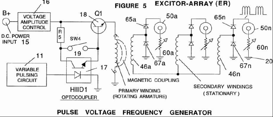
A power supply system utilizes a generator as a source of fuel to separate hydrogen and oxygen gases from natural water. It has the capability to control gas production by varying the amplitude of the voltage and/or the pulse...
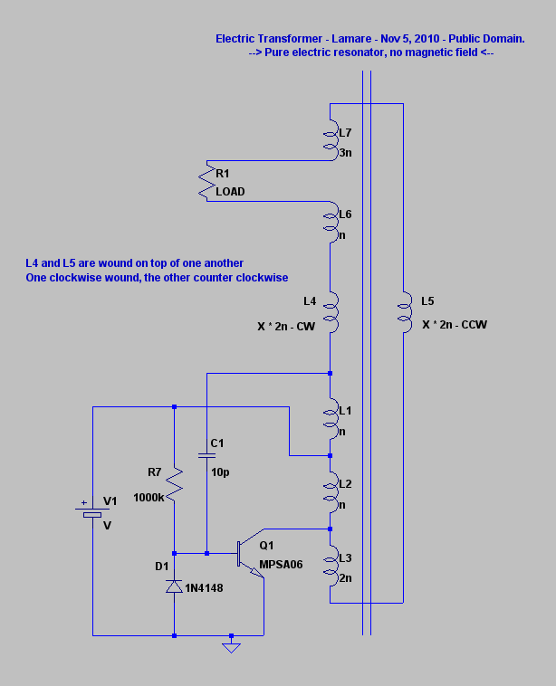
The principle involves a parasitic capacitance between coil windings that stores energy. By utilizing bifilar winding for the coil, a significantly larger voltage difference is achieved between adjacent windings, resulting in increased energy storage in these parasitic or self-capacitances....
The TS2418 is a monolithic integrated circuit telephone tone ringer that utilizes a bridge diode. When paired with an appropriate transducer, it serves as a replacement for traditional electromechanical bells. This device is compatible with either a piezo transducer...
This FET audio mixer exemplifies the versatility of Field Effect Transistors (FETs). Although FETs were originally designed for high-frequency applications, they are also highly effective in audio frequency applications. The circuit can accommodate an unlimited number of inputs, provided...