
Beginners Guide AVR Programming

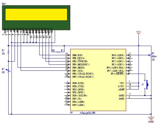
The schematic for this project outlines a basic microcontroller circuit utilizing the Atmel AVR Atmega16, which serves as the central processing unit. The circuit board will act as the foundation for mounting the components and establishing electrical connections.
The Atmega16 microcontroller is an 8-bit device featuring 16 kilobytes of programmable flash memory, 1 kilobyte of SRAM, and 512 bytes of EEPROM. It operates at a maximum clock frequency of 16 MHz and provides a range of I/O pins for interfacing with other components.
The eight 330-ohm resistors are typically used for current limiting in various parts of the circuit, such as LED indicators or pull-up/pull-down configurations for input pins. Each resistor should be connected in series with the components that require current regulation to prevent damage due to excessive current flow.
To assemble the circuit, the following steps are recommended:
1. Begin by securing the circuit board to a stable work surface.
2. Insert the Atmega16 microcontroller into the designated position on the board, ensuring that the orientation aligns with the pin configuration specified in the datasheet.
3. Place the 330-ohm resistors in their respective locations on the board, adhering to the schematic layout to maintain proper connectivity.
4. Utilize a soldering iron to connect the components to the circuit board, ensuring that each joint is solid and free of shorts.
5. After soldering, verify the connections against the schematic to confirm correct placement and orientation of all components.
Once the assembly is complete, programming the Atmega16 with the desired firmware can be accomplished using an appropriate programmer. This allows the microcontroller to execute specified tasks, enabling the circuit to function as intended. Proper testing and troubleshooting should follow to ensure that all components operate correctly within the circuit.You will get this done in 30 min. Step 1: Parts 1. 1 X any type of circuit board 2. 1 X Atmel AVR Atmega16 microcontroller 3. 8 X 330 ohms Resistors 4. 🔗 External reference
Related Circuits
This document provides a guide on understanding a simple computer system and its operation. It will examine the BASIC programming language and its statements, enabling communication with external circuitry. The document will also explore how to interface electronic circuits...
A straightforward tutorial on utilizing the ADC (Analog to Digital Converter) unit of the AVR microcontroller, demonstrated with the Atmega8, including a circuit diagram and code examples. The ADC unit in the Atmega8 microcontroller is a crucial component that allows...
A collection of Kenwood TK-760G-1 transceivers (two-way radios) was programmed to a single channel, with all other features locked. Various programming software for Kenwood was gathered from the internet and local newsgroups, but a programming cable was required. The...
Ethernet has traditionally been a complex interface. All Ethernet chips up until now have had 100 pins or more, making them difficult to find in small quantities and challenging to use with microcontrollers that have limited memory. Microchip has...
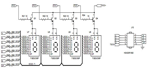
A seven-segment display is a fundamental electronic display device capable of showing digits from 0 to 9. The most prevalent configuration consists of an array of eight LEDs arranged in a specific pattern to represent these digits, typically laid...
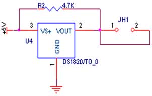
The circuit demonstrates the interfacing of the DS1820 temperature sensor with a microcontroller. The first pin of the sensor is connected to ground (GND), the third pin is connected to the power supply (VCC), and the second pin is...