
Blinking LEDs to Music

The described project is an audio-activated LED circuit that visually responds to sound signals. The circuit typically consists of an audio input stage, a signal processing unit, and an output stage that drives the LEDs.
The audio input stage can utilize a microphone or a direct connection to an audio output from devices such as smartphones or computers. A simple preamplifier may be included to amplify the audio signal, ensuring that it is strong enough for further processing.
The signal processing unit commonly employs a rectifier circuit to convert the AC audio signal into a DC signal. This DC signal can then be fed into a comparator or a microcontroller, which determines the amplitude of the audio signal. By analyzing the audio signal's characteristics, the circuit can differentiate between beats and quieter sections of the audio.
The output stage is where the visual effect occurs. This stage typically consists of a series of LEDs connected to a transistor or a relay that acts as a switch. When the signal exceeds a certain threshold, the transistor is activated, allowing current to flow through the LEDs and causing them to blink. The arrangement of the LEDs can vary, with options for sequential lighting, color changes, or patterns, depending on the complexity of the circuit design.
Power supply considerations are essential; the circuit can be powered by batteries or a DC power adapter, ensuring that the voltage levels are compatible with the components used. Proper grounding and circuit protection measures should also be implemented to prevent damage from voltage spikes or incorrect connections.
Overall, this project not only serves as a practical application of basic electronic principles but also offers an engaging way to visualize audio signals through LED light displays.This is a fairly simple project for anyone with some electronic skills. Plug this circuit into an audio source and the LEDs will blink to the rhythm o.. 🔗 External reference
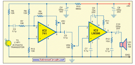
Related Circuits
This circuit generates audio musical notes that can be heard from a distance of up to 10 meters. The circuit is divided into two parts: an infrared (IR) music transmitter and a receiver. The circuit operates on the principle of...

IC1, a 555 timer, is configured as an astable multivibrator to generate a signal that triggers IC2, a 7490 decade counter. This counter produces a BCD output that is connected to IC3, a 7445 BCD-to-decimal decoder/driver. The output from...

This circuit generates audio musical notes that can be heard from a distance of up to 10 meters. It consists of two main components: an infrared (IR) music transmitter and an IR music receiver. The IR music transmitter operates...

This slideshow is based on the LED Design Ideas Collection, which features a compilation of LED-related circuits and design applications submitted by readers and published in EDN's Design Ideas section. Users can browse through the circuit schematics in this...

Here is a schematic of a rechargeable 9-LED flashlight using two Gates SLA cells and nine LEDs. It is as bright as when the single bulb was used, and lasts 3 times longer per charge. That is about 10...

This circuit is designed to produce a musical horn whenever a car is in reverse gear. It utilizes two integrated circuits (ICs) for its operation: a voltage regulator (7805, referred to as IC1) and a musical tone generator (UM66,...