
Booster circuit

The described circuit operates on the principle of boosting a low-voltage signal to a higher voltage level using a combination of an NE555 timer, a transistor, and a transformer. The NE555 timer is configured in astable mode to generate a continuous square wave output. This oscillating signal is crucial for the operation of the subsequent components.
The VT transistor serves as a switch that modulates the current flowing through the primary winding of the booster transformer. When the NE555 timer outputs a high signal, the transistor turns on, allowing current to flow through the transformer. This current induces a magnetic field in the transformer core, which is essential for transferring energy to the secondary winding.
The transformer is designed to step up the voltage, meaning that the output voltage across the secondary winding will be significantly higher than the input voltage applied to the primary winding. The turns ratio of the transformer determines the magnitude of this voltage increase.
After the signal has been stepped up by the transformer, it is still in an AC form. A rectifier circuit, typically composed of diodes, is used to convert the AC voltage into a pulsating DC voltage. Depending on the design, additional filtering components, such as capacitors, can be included to smooth the rectified output, resulting in a more stable DC voltage.
This simple boost circuit is often utilized in applications requiring higher voltage levels from a lower voltage source, such as in battery-powered devices or in scenarios where compact, efficient power conversion is necessary. The design's effectiveness relies on the careful selection of components, including the NE555 timer configuration, the specifications of the transistor, and the characteristics of the transformer used.It illustrates a simple boost circuit, which is supplied by an oscillating signal generated NE555 via VT transistor to drive booster transformer , a step-up transformer to increase the oscillation signal is then rectified DC high voltage can be obtained.
Related Circuits
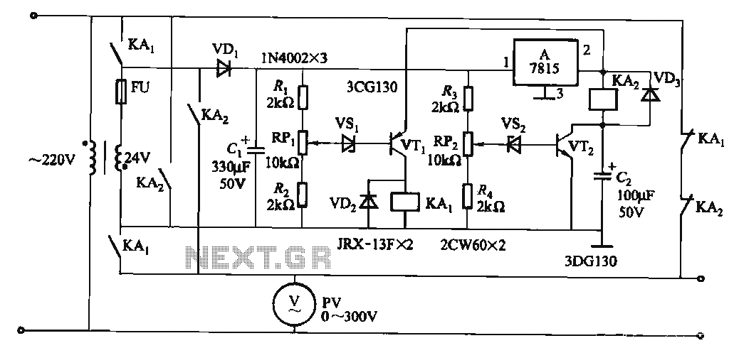
When the input voltage is in the range of 170-260V AC, the output AC voltage falls between 187-231V. The transformer ratio is k = 24/220 = 0.11. If the input voltage drops below 170V, relay KAi activates (adjusted by...
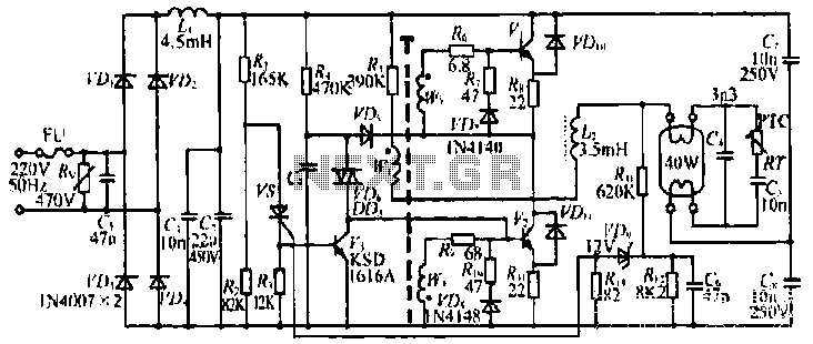
The figure illustrates the input from the varistor, which serves an overvoltage protection role. Components VDi and VD4 function as rectifiers, while L1 and C2 are utilized for filtering. The circuit comprises R, C9, and VD6, which are part...
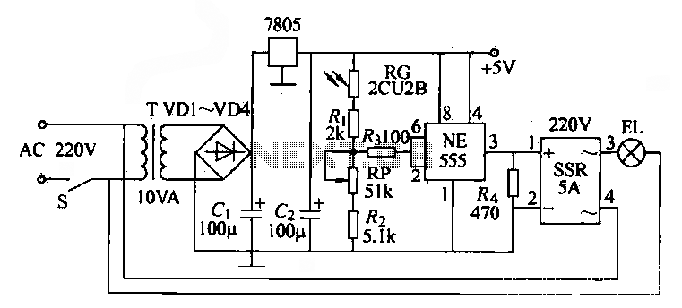
The NE555 time base circuit with an AC solid-state relay (SSR) can function as an automatic light switch circuit. The circuit diagram illustrates that during the day, the incandescent light is turned off due to the influence of the...
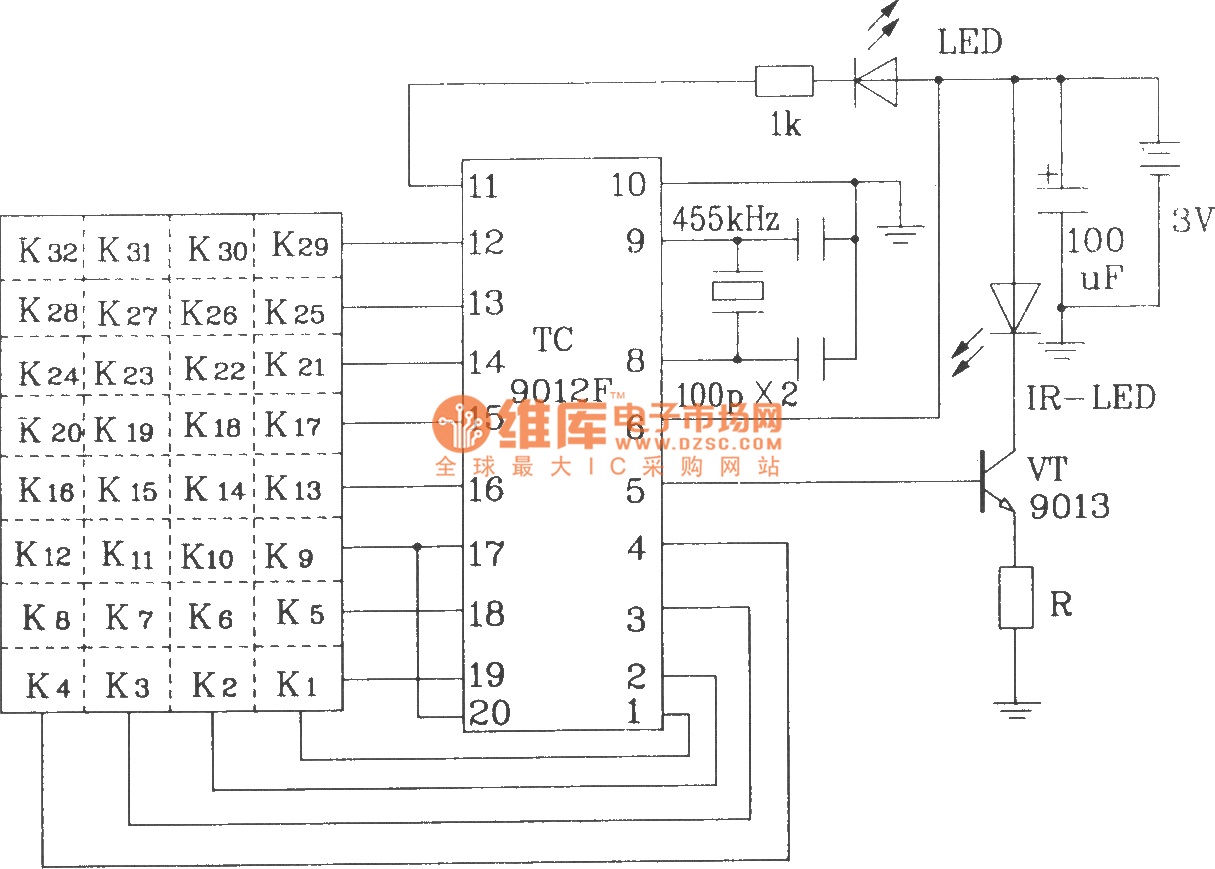
The TC9012 is a specialized off-screen remote control code transmitter. It incorporates an oscillator, divider timing generator, system code latch, data storage, key scan input, key scan output, and carrier control and output units. The internal 8-bit system code...
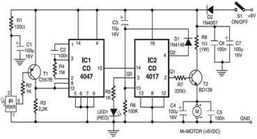
The following circuit illustrates an infrared toy car motor controller. This circuit is based on the 4047 and 4017 integrated circuits (ICs). Features: 16V. The infrared toy car motor controller circuit utilizes two primary integrated circuits, the 4047 and the...
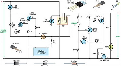
This circuit is designed to switch power to a Peltier cooler in a vehicle. Power is supplied to the load from the vehicle's battery when the ignition switch is on and from an SLA auxiliary battery when the ignition...