
Broadcast band RF amplifier

The circuit described employs a frequency response that is essential for various audio and RF applications, allowing it to effectively amplify signals within the specified range. The use of a field-effect transistor (FET) in the common-source configuration provides high input impedance and significant voltage gain, making it suitable for interfacing with high-impedance sources. The optional resistor R1 plays a critical role in defining the input impedance, which can be tailored to suit specific requirements, enhancing the circuit's versatility.
The direct coupling of the signal to Q2 ensures minimal signal loss and maintains the integrity of the amplified output. The common-base configuration of Q2 is particularly advantageous for achieving high-frequency performance, as it offers low input capacitance and improved bandwidth. This configuration allows for effective isolation between the input and output stages, which is vital for preventing feedback and ensuring stable operation across the frequency range.
Q3, functioning as an emitter follower, provides a low output impedance, which is crucial for driving subsequent stages or loads without significant signal degradation. The typical output impedance of around 50 ohms makes it compatible with standard RF and audio applications. The inclusion of resistor R8 allows for adjustments to the output impedance, enabling the circuit to interface with various loads or to match specific requirements in different applications.
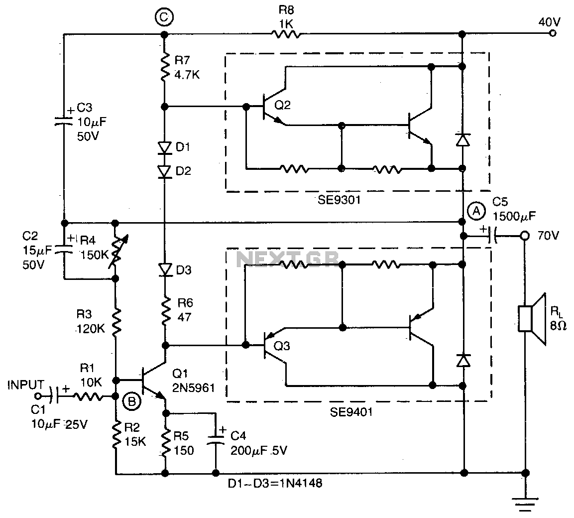
In scenarios where higher output impedance is necessary, the formula R8 - Rout - 50 provides a straightforward method for calculating the required resistance. Alternatively, connecting output capacitor C4 directly to the emitter of Q3 allows for a simplified output stage, which may be preferable in certain designs where impedance matching is not critical. This flexibility in design choices enhances the overall functionality and adaptability of the circuit for diverse electronic applications.The circuit has a frequency response ranging from 100 Hz to 3 MHz; gain is about 30 dB. Field-effect transistor Ql is configured in the common-source self-biased mode; optional resistor Rl sets the input impedance to any desired value. Commonly, it will be 50 ohms. The signal is then direct-coupled to Q2, a common-base circuit that isolates the input and output stages and provides the amplifier's exceptional stability.
Q3 functions as an emitter follower, to provide low output impedance (about 50 ohms). For higher output impedance, include resistor R8. It will affect impedance according to this formula: R8 - Rout-50. Otherwise, connect output capacitor C4 directly to the emitter of Q3.
Related Circuits
This preamplifier is a requirement resulting from many friends to provide a high-quality preamplifier, capable of driving high-quality power amplifiers with good sound. It is not, however, difficult to make; it combines simplicity and handiness. It does not allocate...
This simple and inexpensive audio amplifier can be constructed using a couple of TO-220 monolithic Darlington transistors for the push-pull output stage. The frequency response is flat within 1 dB from 30 Hz to 200 kHz, with typical harmonic...
The three circuits described provide a constant current to the LED (or LEDs) when the supply voltage reaches 15V or higher. The second and third circuits can be activated or deactivated through the input line by turning on the...
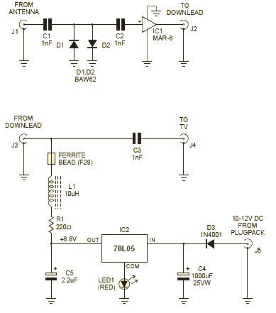
This wideband amplifier circuit is designed using the MAR-6 IC manufactured by Mini Circuits. The MAR-6 VHF-UHF wideband amplifier circuit provides a stable gain of at least 9 dB up to 2 GHz. Since the MAR-6 is designed to...
This class-D audio amplifier is suitable for TV and home stereo systems. The TDA7882 integrated circuit (IC) provides a class-D audio amplifier solution. Since this IC has a single channel output, two units are required for stereo applications. The...
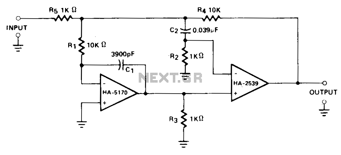
A composite configuration significantly reduces errors without compromising the high-speed, wideband characteristics of the HA-2539. The HA-2540 can also be utilized, although it exhibits slightly lower speeds and bandwidth response. The HA-2539 amplifies signals above 40 kHz, which are...