
Broken Charger-connection Alert

The circuit described functions as a load detection mechanism for battery chargers and plug-in adapters. Its primary purpose is to ensure that the load, which could be a set of batteries or any low DC voltage device, is properly connected to the power supply. This is crucial for preventing damage to both the power source and the load due to incorrect connections.
The circuit operates within a voltage range of 3 to 15 volts and can handle a maximum current of 1 ampere. It is important to note that the supply voltage must be at least one volt higher than the voltage required by the load to ensure proper functionality. This voltage differential is necessary for the circuit to effectively detect the presence of the load.
In terms of operation, the circuit is placed in series between the power supply and the load. This configuration allows it to monitor the current flow to the load. If the load is disconnected or improperly connected, the circuit will detect a drop in current flow. This change can be indicated through various means, such as an LED indicator or a relay that can trigger an alarm or a shutdown mechanism.
The design of the circuit may incorporate components such as resistors, transistors, and diodes to manage the detection process. A resistor can be used to limit the current flowing through the circuit, while a transistor can act as a switch to control the indicator or relay based on the detected current level. Diodes may be included to protect the circuit from reverse polarity or voltage spikes.
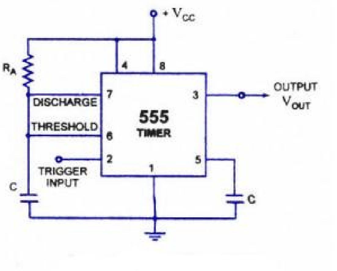
Overall, this load detection circuit is a valuable tool for ensuring the safe and effective operation of battery chargers and similar devices, providing an essential safeguard against improper connections.The above circuit can be useful to detect if the load of any battery charger or plug-in adaptor supply is not properly connected. The load can be a set of batteries to be charged or any other type of battery or low dc voltage operated device.
The circuit can safely operate over a 3 to 15V range and 1A max. current, provided the supply voltage is about one volt higher than the voltage required by the load. Circuit operation: The circuit is inserted between the supply and the load, therefore 🔗 External reference
Related Circuits
The following circuit illustrates a Mains Remote-Alert Circuit Diagram. Features include simple circuitry, with the transmitted signal being conveyed effectively. The Mains Remote-Alert Circuit is designed to provide a notification system that alerts users about the status of mains power....
The concept for this circuit originated when a pet dog began barking persistently upon detecting a moving shadow, possibly that of an intruder. Dogs possess a night adaptation capability that enhances their vision sensitivity in low-light conditions, allowing them...
This circuit emits an intermittent beep or flashes an LED when the water level in a container reaches a predetermined height. It is designed to be mounted on top of the container, such as a plastic tank, using two...
This circuit is designed to alert the vehicle driver when the maximum fixed speed limit is reached, such as on a motorway. It eliminates the need for the driver to look at the tachometer, reducing distraction while driving. The...

When power is applied to the circuit, the heater coil in the sensor is energized by the 5-V output of IC5, a 7805 voltage regulator. Breathing into the sensor with alcohol on one's breath will lower the sensor's resistance;...
The lighting system of a motor vehicle comprises lighting and signaling devices mounted or integrated at the front, sides, rear, and sometimes the top of the vehicle. This system's purpose is to provide illumination for the driver to operate...