
Buick LeSabre

The circuit in question involves a control unit that manages the operation of a blower motor via a relay. The relay serves as an interface between the control unit and the blower motor, allowing for various operational states based on user input. When the control unit is OFF, the relay remains in a normally open state, preventing current flow to the blower motor. When any of the operational buttons are pressed, the control unit applies a ground signal to the relay, energizing it and allowing current to flow through to the blower motor.
The control unit's internal architecture may involve either mechanical switches or transistors to manage the ground signals. If mechanical switches are used, they may be configured in a multi-pole arrangement, where the OFF position is open (no current flow) and all other positions close the circuit, providing a ground signal. If transistors are employed, they would act as electronic switches, allowing current to flow when activated by the control unit.
For troubleshooting, if the ground signal to the blower speed relay is found to be intermittent, it may be beneficial to create a permanent ground connection. This could be achieved by jumpering the control wire (C3-H) directly to a known good ground (C2-H). This modification would bypass the control unit's switching mechanism, providing a continuous ground to the blower speed relay. However, it is advisable to incorporate an under-dash toggle switch to maintain control over the blower operation, allowing the user to manually disconnect the circuit when necessary.
In terms of replacement units, inquiries regarding compatibility among AC Delco part numbers should be directed to a qualified parts dealer or manufacturer. For repairs, contacting an authorized AC Delco service center is recommended, as they would have access to the necessary schematics and components for effective repairs. Access to the circuit board schematic would provide further insight into the internal workings of the control unit and assist in diagnosing potential issues with the ground signal.This line provides ground to that relay and is N-O when CU is OFF, and is N-C for all other control functions. The Off switch on the CU is "sticky" as I mentioned before. Several questions: 1) Can I substitute AC Delco CU p/n 15-71886 or p/n 15-71932 for p/n 15-71887 (GM #16145214), if one or the other is easier to find All three units have the same mounting tabs
and show the same push-buttons in a different configuration on the front. 2) Is the switch that controls ground to the blower speed relay an internal transistor If so, which one 3) I`m not inclined to want to spend $250-500 for a replacement CU, even if I can find one in the free world. Is there an AC Delco electronics service center that can repair the unit Where would I find it on-line 4) Barring finding a replacement CU at a reasonable price, where would I jumper the control line to the blower speed relay to a different ground to create a permanent ON signal to the blower resistor Can I jumper it to the ground line (known good) on the C2 connector that connects ground to the CU itself I think I did.
As I said above, the control line (ground) from the dashboard control unit to the blower speed relay is intermittent (95% sure this is the fail point). This line applies a ground signal to the blower speed relay which controls the blower. It is controlled by a switch of some kind on the control unit circuit board. I don`t know if the switch is a multi-pole switch that is hardwired to the bank of eight buttons on the control unit (with OFF being an open [no ground signal applied ~ relay not energized] and all other buttons being closed [ground signal applied ~ relay energized]), or it may be a transistor that has one leg wired to the seven front panel buttons that control AC/heat.
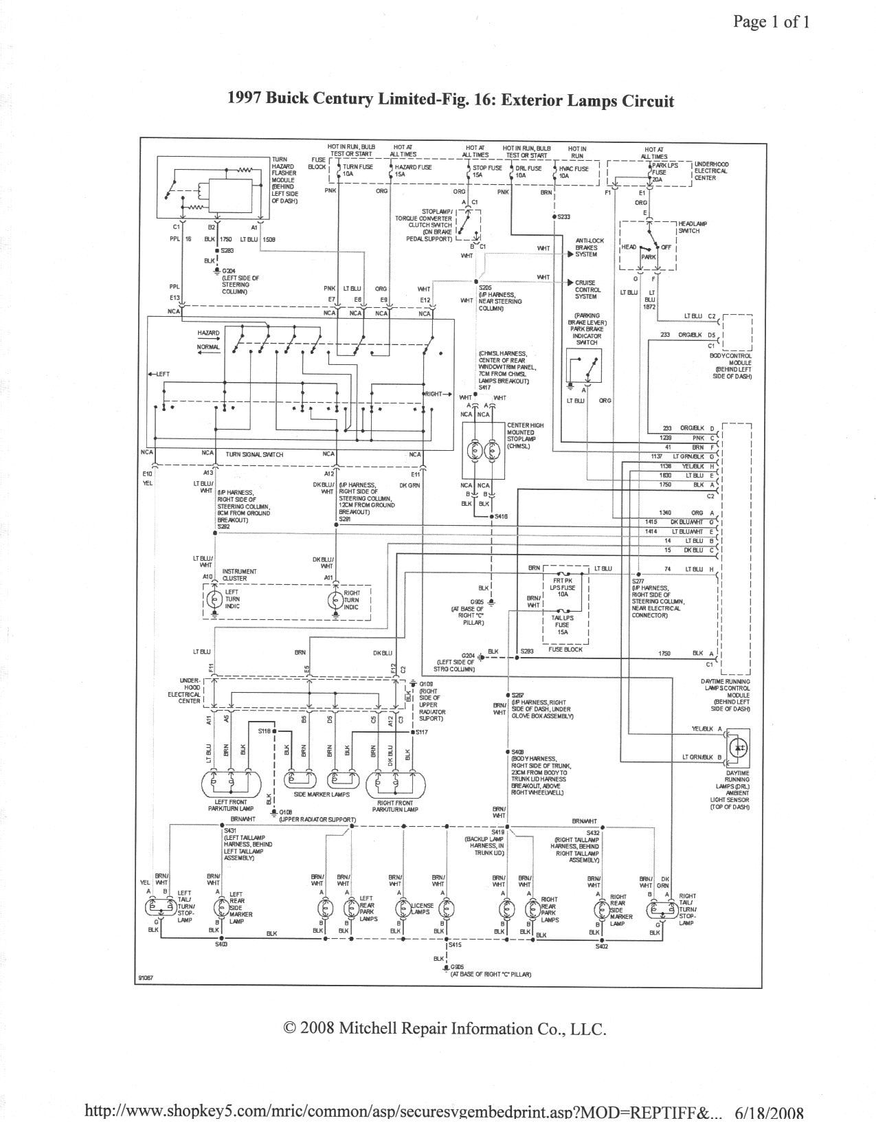
Do you know If this is a manual system my info shows that the controller is suppling voltage to the resister and the blower is dirrectly grounded so I need to know for sure what it is See attached circuit diagram. Voltage is supplied to both the fan speed selector switch on the CU and to the blower resistor through the blower speed relay.
The control wire on the CU (C3-H) supplies ground to the relay, which activates the solenoid and closes the switch to provide power through the resistor to the fan. Do you have access to the control unit circuit board schematic If so, could you upload it Alternately, would you advise a jumper from C3-H (control) to C2-H (ground) to create a permanent ground condition to the blower speed relay Note: I would include an under-dash toggle switch.
Oh ok yes I follow you now, I was not catching what you were saying. I do not have a schematic of the circuit board, you could only get that from the manufacturer. As for adding a toggle switch yes that should work. Ask-a-doc Web sites: If you`ve got a quick question, you can try to get an answer from sites that say they have various specialists on hand to give quick answers. Justanswer. com. Traffic on JustAnswer rose 14 percent. and had nearly 400, 000 page views in 30 days. inquiries related to stress, high blood pressure, drinking and heart pain jumped 33 percent. 🔗 External reference
Related Circuits

Converting a 1958 Buick to electric wipers with delay and automatic "wipe on wash" functionality while integrating the new electrical components with the original non-electric wiper controls to maintain a consistent driver experience. The conversion process is ongoing, and...
In this diagram, check for battery voltage at specific points. It is not necessary to check every point, just enough to confirm that all areas have power. Fuses 22 and 23 are blown; replacing them is advisable, though they...
A 1999 Buick Regal has experienced a failure of the instrument panel lights. An examination of related fuses, including those unrelated to lighting, revealed no faults. Inquiry was made about the existence of a circuit breaker behind the headlight/interior...
It is essential to ensure that none of the light bulbs on the vehicle are burnt out, particularly the turn signal lights, brake lights, and dashboard indicator lights. Malfunctions can occur when bulbs are burnt out. Utilizing the exterior...