
Build a Portable AM Radio Transmitter

The A-1 Minicaster circuit is designed around the 1A7 vacuum tube, which serves as the primary active component in this portable transmitter. The circuit operates on a battery voltage of approximately 1.5 volts, making it suitable for portable applications. The connections for the tube's pins are as follows:
- Pins 1 and 2 are connected to ground, serving as the base shell and the A- terminal, respectively.
- Pin 3, designated for the plate, connects through an RF choke of greater than 1 mH to the B+ voltage source, with a capacitor of 0.01 µF leading to the antenna terminal. This arrangement helps to filter and stabilize the RF output.
- Pin 4, the screen grid, is connected through a 47 kΩ resistor to B+ and has a 0.05 µF capacitor to ground, which aids in maintaining a stable screen voltage.
- Pin 5, the oscillator grid, is linked to ground through a 220 kΩ resistor, and a 0.001 µF capacitor connects to the secondary winding of the oscillator coil, with the other end grounded. This configuration is essential for the oscillator to function effectively.
- Pin 6 connects the primary of the oscillator coil to B+, facilitating oscillation.
- Pin 7 is connected through one half of a double-pole single-throw (DPST) switch to the positive voltage, while the other half of the switch connects to B+. This switch allows for easy power control.
Additional features include a neon indicator (NE-2) across the B+ line to signal when the device is powered on. A low-resistance load, typically between 8 to 24 ohms, can be switched in or out across the RCA jack to ensure proper impedance matching with the audio source, such as a pocket-sized tape recorder. The overall construction of the A-1 Minicaster was creatively accomplished using an old cake pan, demonstrating a practical approach to building a functional radio transmitter.
This project is intended for non-commercial use by radio hobbyists, allowing for personal reproduction and experimentation with the provided instructions and schematic. Commercial exploitation of this design is strictly prohibited.After we published the original Li`l 7 AM Transmitter plans, fellow experimenter Scott Todd sent us information about his design for a similar portable, battery-powered transmitter. -Original Message- From: Scott Todd Sent: Wednesday, April 12, 2000 8:58 AM To: Walter Heskes Subject: A-1 minicaster I noticed that you have yet to get around
to developing a battery operated part 15 transmitter for swap meets (or if you have, it`s not on the net. ) Well, I decided to take matters into my own hands and did one myself. Actually it was nothing more than a variation on a converter circuit in a farm radio using a 1A7 (hence the name A-1 Minicaster.
) Since I`m no computer genius and don`t own a scanner, I`ll have to describe the schematic. Should be simple enough- Pins 1 & 2 [base shell and A- respectively] to gnd. Pin 3 [plate]- RF choke >1mH (will be replacing with tuned circuit for better performance and lower spurious output) to B+, and. 01 to antenna terminal. Pin 4 [screen] through 47K to B+, and. 05uF cap to gnd. Pin 5 [osc. grid]- 220K to gnd, and. 001u cap to secondary of osc. coil; other end of same to gnd. Pin 6 [osc "plate"]- primary of osc. coil to B+. Pin 7 through 1/2 DPST sw. to +1. 5v. The other half of the DPST switches B+. Cap grid- 1M ohm to gnd, and >/=. 05uF cap to input jack (RCA). Additional touches- NE-2 neon indicator across B+ for power on; a low resistance (8-24ohm) that can be switched in or out as needed across the RCA jack for proper loading of audio source, such as when using a small pocket size tape recorder speaker output jack for source of programming.
Built mine on an old cake pan that developed holes and was no longer useable. Scott Todd N0BST -Original Message- From: Scott Todd Sent: Wednesday, April 26, 2000 8:24 AM To: Heskes, Walter M. Subject: RE: A-1 minicaster Here`s the pix of the A-1 minicaster, top and bottom plus schematic. I didn`t have a DP switch, so I had to kluge a second SP underneath for the HV. Note the neon indicator for HV-on. Small cap to osc grid is. 001 (noticed it was too small to read on schematic. ) This radio construction project, including all descriptions, diagrams, photos, and the underlying electronic design, is published here for the noncommercial use of radio hobbyists.
You may print and reproduce these project instructions for your personal use. Commercial use of this material is strictly forbidden. 🔗 External reference
Related Circuits
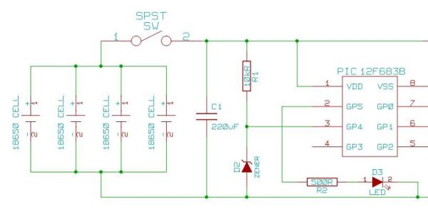
Heavy-duty portable charger for USB devices (phones, iPad, etc.). Have you ever needed to charge your phone on the go? Unable to find a wall socket to charge your iPod?.. The heavy-duty portable charger is designed to provide a reliable...
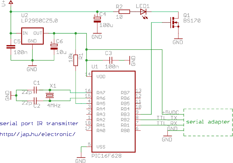
This is a programmable infrared (remote control) transmitter, which can be controlled from a PC serial port. It is capable of sending many remote control formats, including the Philips RC-5 standard. Exact formats with the timing parameter names are...
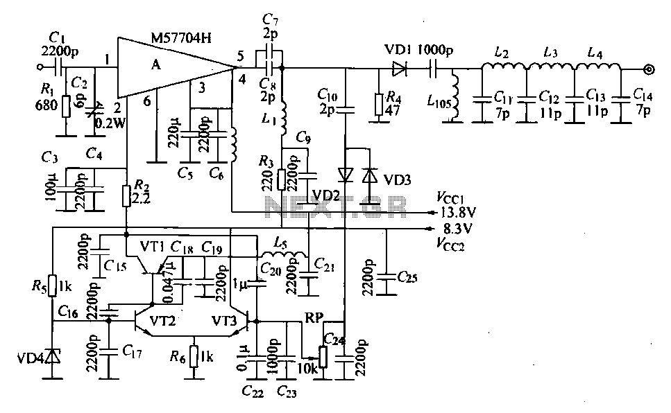
The FM radio transmitter is a high-frequency amplifier circuit that utilizes the Mitsubishi frequency set, specifically the M57704H discharge path. It operates within the frequency range of 457-458 MHz and has a transmission power of 5 watts. As illustrated...
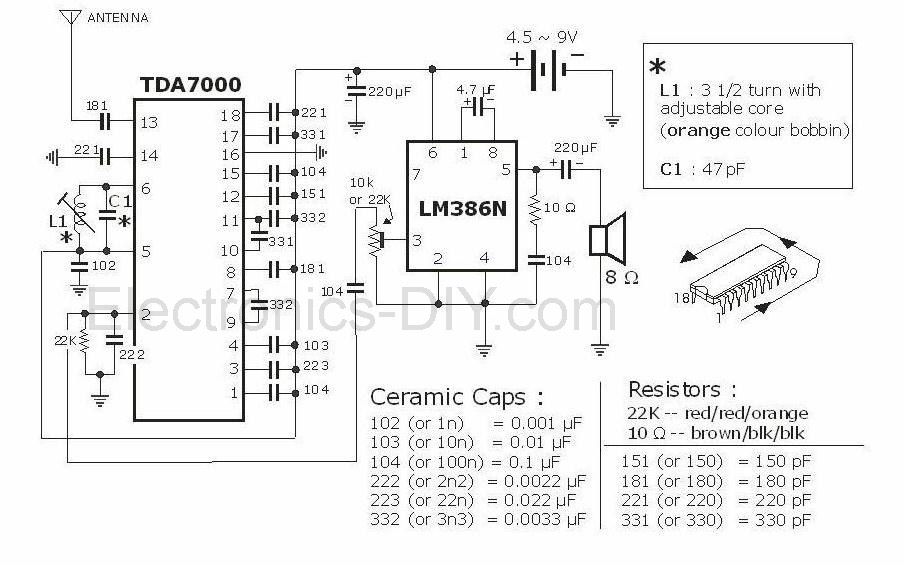
This project is an FM radio utilizing the TDA7000 and LM386 integrated circuits. The TDA7000 IC is notable for its operation as a complete FM superheterodyne receiver, incorporating the standard components such as a local oscillator, mixer, intermediate frequency...
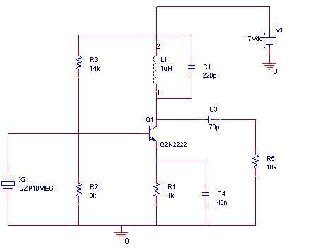
A simulation of a 27 MHz transmitter circuit is to be conducted using PSPICE. The circuit diagram is provided as Figure 1 in the following content. The 27 MHz transmitter circuit typically consists of several key components, including an oscillator,...
The most commonly available headphones have an impedance of 2 × 32 Ω. This relatively low value makes them unsuitable for certain designs. However, with some clever modifications, these headphones can be adapted for such applications. To achieve this,...