
Capacitance-meter

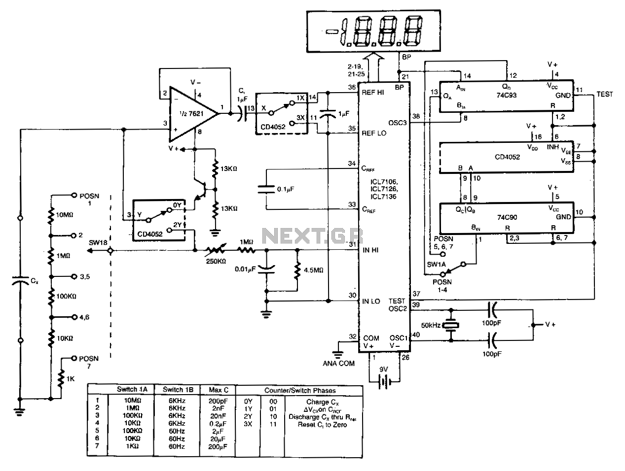
U1a serves as an oscillator, while U1b functions as the measurement component of the circuit. It converts an unknown capacitance into a pulse-width modulated signal, similar to the operation of an automotive dwell meter. The meter is linear, meaning that the fraction or percentage of time the output is high is directly proportional to the unknown capacitance (CX in the schematic). Meter M1 measures the average voltage of these pulses, as its mechanical frequency response is low compared to the oscillator frequency of U1a.
The circuit employs a dual operational amplifier configuration, where U1a generates a square wave signal at a frequency determined by external resistors and capacitors connected to its input. This square wave output is then fed into U1b, which is configured to measure the pulse width of the signal. The relationship between the pulse width and the unknown capacitance is established through a calibrated reference, allowing for accurate capacitance measurement.
The pulse-width modulation (PWM) technique used in this circuit is advantageous because it provides a linear relationship between the duty cycle of the output signal and the capacitance being measured. This linearity is crucial for precise readings, enabling the circuit to function effectively as a capacitance meter. The output from U1b is then processed by Meter M1, which averages the voltage levels of the PWM signal, yielding a direct indication of the unknown capacitance.
The design of the circuit should also consider the bandwidth and response time of Meter M1, ensuring that it can accurately track the rapid changes in the PWM signal generated by U1a. Proper filtering may be necessary to smooth out the output signal, enhancing measurement stability and accuracy. Additionally, the choice of components, such as the operational amplifiers and passive elements, must align with the expected operating range of the circuit to ensure reliable performance.U1a is an oscillator and U1b tbe measurement part of tbe circuit. It converts unknown capacity into a pulse-width modulated signal the same way an·automotive dwell meter works. The meteris linear so tbe fraction or percentage of time that tbe output is high is directly proportional to the unknown capacitance (CXin the schematic).
Meter M1 r€ads the average voltage of those pulses since its mechanical frequency response is low compared to tbe oscillator frequency of U1a.
Related Circuits
The circuit charges and discharges a capacitor at a crystal-controlled rate and stores the change in voltage achieved on a sample-and-difference amplifier. The current flowing during the discharge cycle is averaged and ratiometrically measured in the analog-to-digital converter (ADC)...