
Capacitance Meter Circuit

A capacitance meter is a specialized device designed to measure the capacitance of capacitors in various electronic circuits. It typically features a digital or analog display that indicates the capacitance value in microfarads (µF), nanofarads (nF), or picofarads (pF). The operation of a capacitance meter is based on the principle of charging and discharging a capacitor through a known resistor, allowing the meter to calculate the capacitance based on the time constant of the RC circuit.
In a typical capacitance meter circuit, a microcontroller or dedicated IC is employed to control the measurement process. The circuit includes a power supply, often powered by batteries or an external source, and an input terminal where the capacitor to be tested is connected. The meter may also incorporate a range switch to select different measurement ranges, enhancing its versatility for various capacitor types.
The measurement process begins when the user connects the capacitor to the input terminals. The meter applies a voltage to charge the capacitor and monitors the time it takes for the capacitor to reach a predefined voltage level. This time measurement is then processed by the microcontroller, which calculates the capacitance value using the formula derived from the time constant of the RC circuit.
Advanced capacitance meters may offer additional features such as automatic range selection, tolerance measurement, and the ability to test capacitors in-circuit, which can be particularly useful for troubleshooting electronic devices. Some models may also provide a continuity test function, allowing the user to check for short circuits or open connections in components.
Overall, a capacitance meter is an invaluable tool for anyone working with electronic components, providing accurate measurements that are critical for circuit design, repair, and maintenance.Capacitance meter is one instrument that you should have in your toolbox if you are an electronics hobbyist, or if you`re a professional electronic technician . 🔗 External reference
Related Circuits
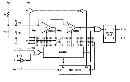
The logic diagram of the CD4538BC Dual Precision Monostable is shown in the following schematic diagram. This IC is a dual, precision monostable multivibrator with independent trigger and controls, according to the datasheet. This CD4538BC IC features a wide...
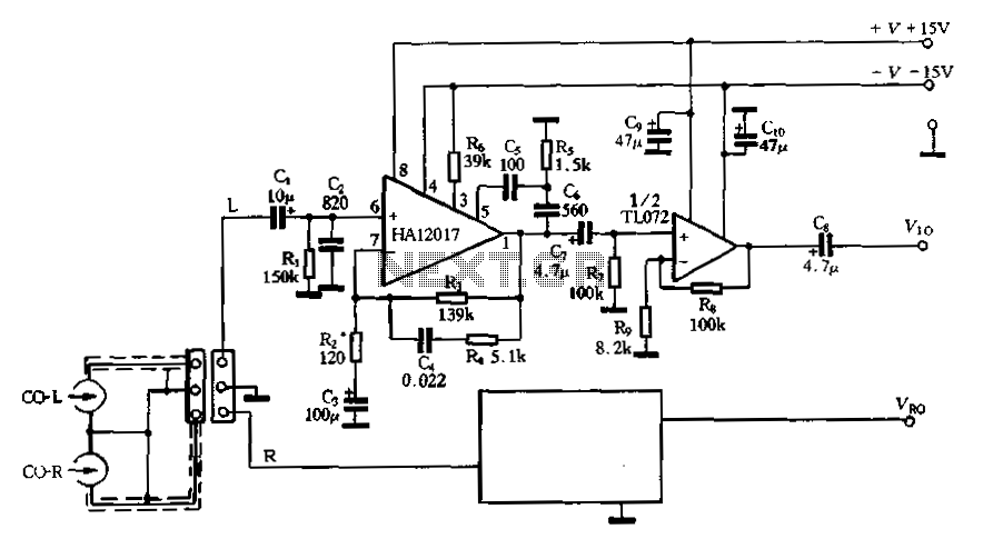
Figure 3-16 illustrates a low-noise preamplifier equalizing circuit using the HA12017. This circuit includes playback components R3, R4, and C4, which conform to a standard balanced network. The gain of the circuit is -7dB at 1kHz, while the output...
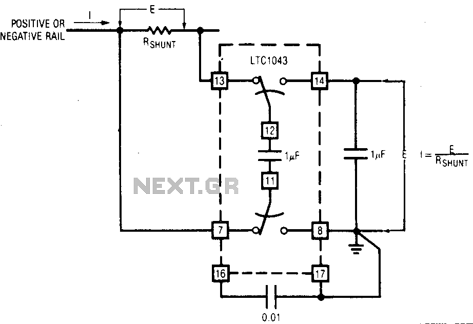
The LTC1043 can be induced through any of its current shunt supply rails. Many cells and solar system applications have this feature. If the reference point is grounded, the voltage output of an unloaded amplifier is minimal, allowing the...
Most thefts occur after midnight when individuals enter the second phase of sleep known as paradoxical sleep. An energy-saving circuit has been designed to deter theft attempts by illuminating potential entry points, such as the kitchen or backyard, around...
This lighting solution offers over 90% energy savings compared to incandescent or halogen bulbs, with a lifespan exceeding 50,000 hours. It operates without flickering, making it suitable for human eyes, and produces no RF interference or UV radiation. The...
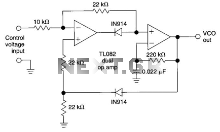
This circuit utilizes the AD639 universal trigonometric function generator from Analog Devices to transform a triangle waveform, which serves as the fundamental waveform of the VCO, into a low-distortion sine wave. By operating the AD639 in its frequency tripler...