
Car Battery 6V or 12V charger circuit

The charging circuit is designed to efficiently manage the charging process of lead-acid or similar batteries, ensuring optimal performance and longevity. The inclusion of transformer T1 is crucial, as it steps down the mains voltage to a lower, safer level suitable for battery charging. The transformer must have a high insulation rating to prevent any risk of electrical shock and must also be robust enough to handle short-circuit conditions without failure.
The circuit typically includes additional components such as rectifiers, voltage regulators, and protection diodes. Rectifiers convert the alternating current (AC) output from the transformer into direct current (DC), which is necessary for charging batteries. The voltage regulator maintains a consistent output voltage, preventing overcharging which could damage the battery. Protection diodes are implemented to prevent reverse current flow, thereby safeguarding the transformer and other circuit components from potential damage.
To enhance charging efficiency, a microcontroller may be integrated into the design to monitor battery voltage and current, allowing for smart charging algorithms that adapt to the battery's state of charge. This feature can help in extending the battery's lifespan by preventing overcharging and optimizing charge cycles.
Overall, the circuit's design should prioritize safety, efficiency, and reliability, ensuring that it meets the necessary standards for battery charging applications. Proper layout and component selection will lead to a robust charging solution suitable for various applications requiring 6V and 12V battery support.This circuit can charge automatically, fast and rightly, batteries 6V and 12V. A basic factor in the success in the circuit operation is the use of transformer [T1] of good quality with very good insulation and resistance in the short circuits.. 🔗 External reference
Related Circuits
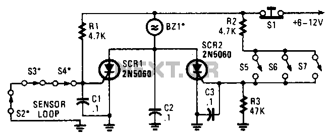
Two SCRs are utilized with two sensor loops. One loop employs series switches, while the other loop employs parallel switches. When a switch is actuated, the SCR is triggered. The alarm is designed to be a non-interrupting type. The circuit...
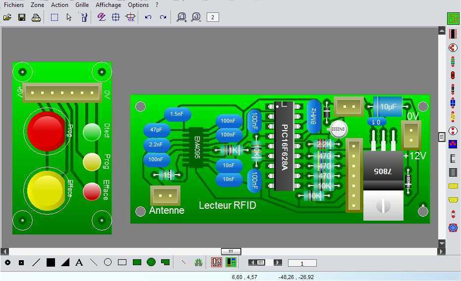
WinCircuit is a software of realization of drawing of printed circuit in single or double layers. Principal qualities are the facility of use and the sight in pseudo 3D which gets a vision of the circuit close to reality....
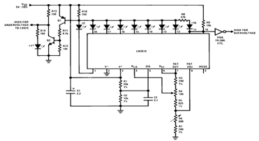
By utilizing several resistors, LEDs, and the LM3914 bar/dot display driver IC, it is possible to create a straightforward 5V voltmeter monitor circuit. This circuit offers TTL-compatible undervoltage and overvoltage warning signals. A complete circuit schematic is available below. The...
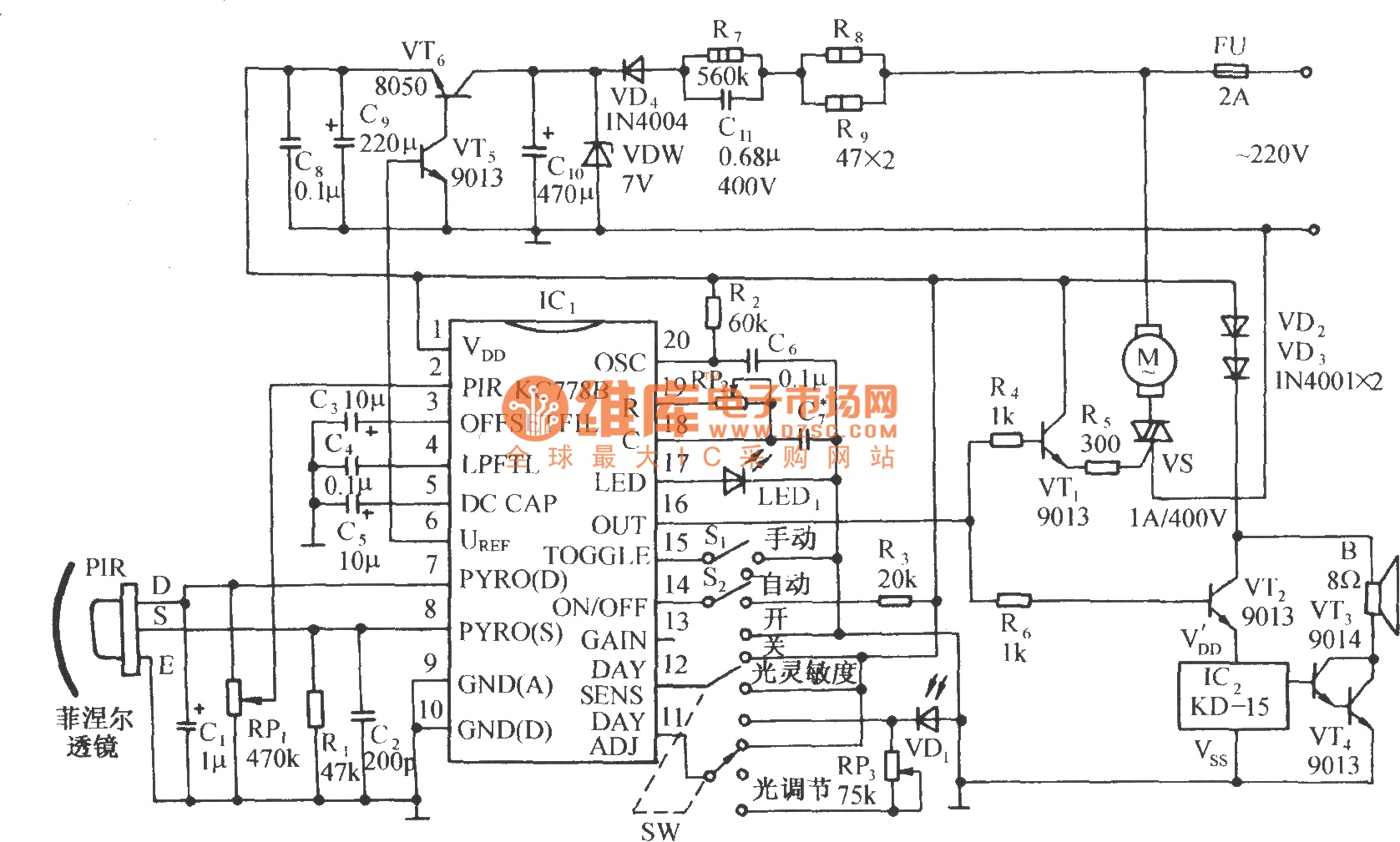
The circuit is depicted in the diagram. It is a control circuit that consists of the infrared-specific integrated circuit KC778B, which serves as the central component. Surrounding it are a pyroelectric infrared sensor head (PIR), a light control and...
This is a differentiator circuit. This circuit can be used to perform differential operations. There are two types of differentiators: the true differentiator and another type. A differentiator circuit is designed to output a voltage that is proportional to the...
The circuit described below is notable for its low power consumption. With a 9V input and no load at the output, it draws only 50 mA, which is significantly lower than the quiescent current of a 78L05 regulator. The...