
car battery monitor with 3 led

The circuit functions as a battery voltage monitoring system using three transistors and three LEDs to provide visual indications of the battery's voltage level.
Transistor Q1, configured as a low-side switch, is responsible for monitoring the battery voltage when it falls below 11.5V. In this state, Q1 conducts, allowing current to flow through LED D1, which lights up to indicate a low battery condition. This feature serves as an early warning for users to recharge or replace the battery.
Transistor Q2 is activated when the battery voltage is between 11.5V and 13.5V. In this range, Q2 operates similarly to Q1 but is designed to indicate a nominal battery voltage. When Q2 turns on, LED D2 illuminates, providing a visual cue that the battery is within an acceptable voltage range. This helps users understand that the battery is functioning properly without immediate attention required.
At a voltage of 13.5V, transistor Q3 is engaged, activating LED D3. This indicates that the battery is fully charged or operating at a healthy voltage level. The use of three distinct LEDs allows for quick visual assessment of the battery's state, enabling users to take appropriate actions based on the battery's condition.
The schematic diagram for this circuit typically includes the three transistors, each connected to their respective LEDs, along with resistors to limit current and protect the components. The circuit may also include a voltage divider or reference voltage source to accurately monitor the battery voltage levels. Overall, this design is effective for simple battery monitoring applications, providing clear visual feedback for battery status.When the battery voltage is 11. 5V or less transistor Q1 is turned on and the LED D1 will be bright. When the battery voltage is between 11. 5 and 13. 5 V, the transistor Q2 is turned on and the LED D2 will light up. When the battery voltage is 13. 5V transistor Q3 will be on the D3 and the LED will light. The schematic diagram come from circuit: Car Battery Monitor with 3 LED power supply. Go to that page to read the explanation about above power supply related circuit diagram. 🔗 External reference
Related Circuits
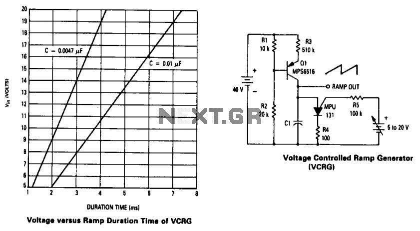
The current source created by Q1 in combination with capacitor C1 determines the duration of the ramp. As the positive DC voltage at the gate varies, the peak point firing voltage of the Programmable Unidirectional Thyristor (PUT) is altered,...
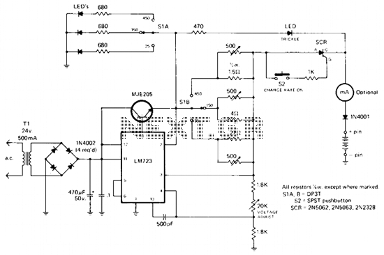
The rectified and filtered voltage from the 24 Vac transformer is applied to the LM723 voltage regulator and the NPN pass transistor configured for constant current supply. A 470-ohm resistor limits trickle current until the momentary pushbutton (S2) is...
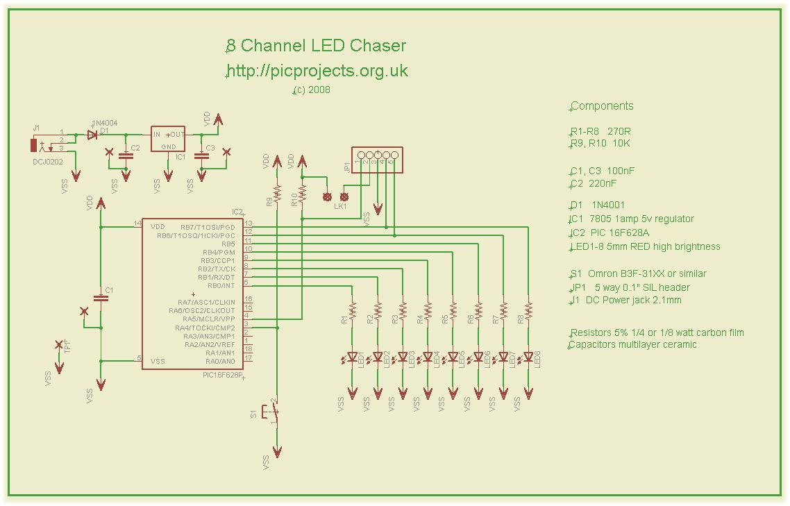
This compact circuit operates 8 LEDs directly driven from a PIC microcontroller, accompanied by a single mode control switch. The firmware controls the LEDs using a 5-bit PWM signal, enabling four levels of intensity for each LED channel: off,...
This document outlines the details of several circuits designed and built for a robot. The first circuit is a voltage regulator intended to supply power to a Raspberry Pi from a 7.2V battery. While the circuit is relatively simple,...
The anti-theft system includes two frequency sirens connected to the vehicle's immobilizer system. In the laboratory simulation model, the changes in operating modes, siren activation, and fuel supply cut-off are indicated by the illumination of LEDs and communicated to...
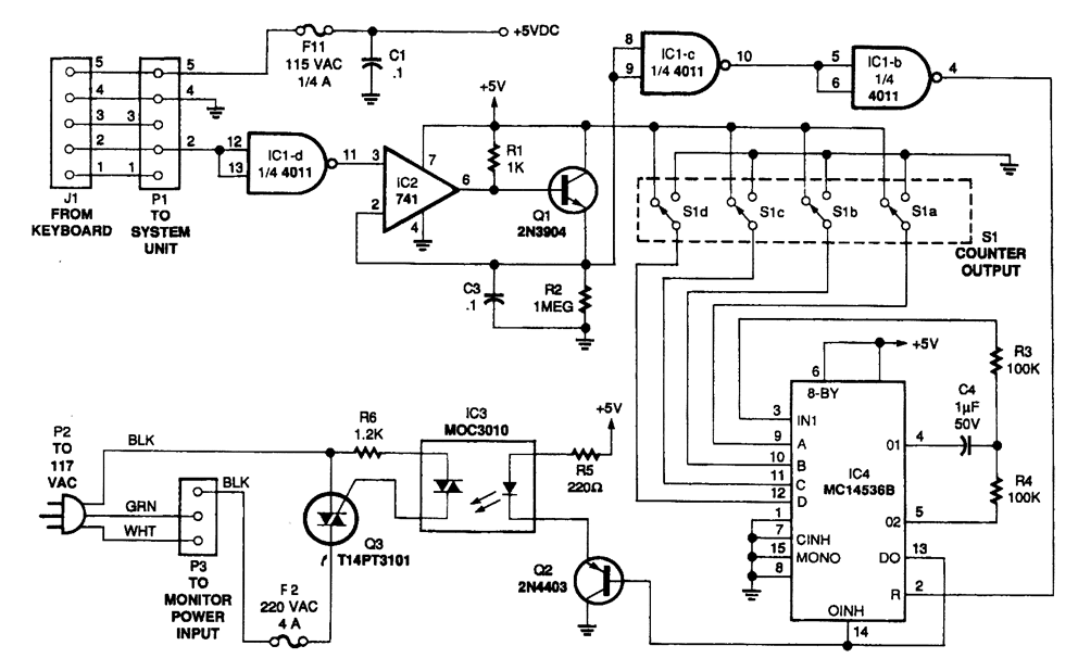
The circuit monitors PC keyboard activity through a five-pin DIN connector J1. When a key is pressed, the keyboard transmits a series of negative-going pulses on pin 2. In conjunction with Q1 and C3, the operational amplifier operates as...