
Car Battery Tester For Cranking Amps Circuit
The described circuit is designed to accurately evaluate the cold cranking amps (CCA) of a battery, which is crucial for assessing the battery's ability to start an engine in cold conditions. The process begins by discharging the surface charge of the battery. This step is essential because surface charge can lead to misleading voltage readings that do not reflect the battery's true state of health.
Once the surface charge is discharged, the circuit employs a constant-current source that draws 2.5 A from the battery. This current draw is significant as it simulates the load that a starter motor would place on the battery during engine cranking. The use of a constant current allows for a controlled environment in which the internal resistance of the battery can be accurately measured.
After maintaining the load for one minute, the circuit measures the voltage drop across the battery terminals. This voltage drop is directly related to the internal resistance of the battery, which can be calculated using Ohm's law. The internal resistance is a critical factor in determining the battery's performance under load, and thus, the cold cranking amps can be derived from this measurement.
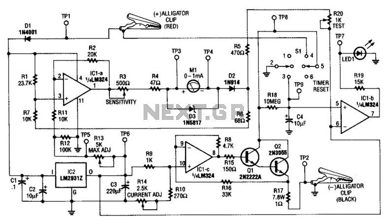
In summary, this circuit provides a reliable method for determining the cold cranking amps of a battery by first eliminating the surface charge and then measuring the internal resistance under a defined load. This approach yields a more realistic assessment of the battery's capability to deliver the necessary current for engine starting, especially in cold weather conditions. This circuit determines the cold cranking amps of a battery by first discharging the surface charge, then checking the internal resistance. This gives a more realistic measurement than simply measuring the instantaneous drop in voltage with a load.
A constant-current source draws 2.5 A. Then, after one minute, a voltage drop measurement is made under load. 🔗 External reference
Related Circuits
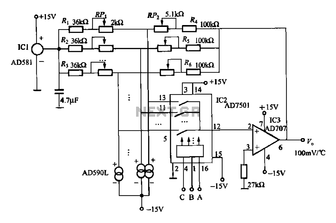
An 8-channel temperature detection circuit capable of monitoring eight different temperature sensors. The D581 serves as a 10.00V precision reference voltage source, providing a stable reference level for the detection circuit. Resistors RPi, RP2, and R4, along with the...

A simple 20-watt amplifier electronic project can be designed using the LM2005 dual high-power amplifier, which is engineered to provide optimal performance and reliability for automotive applications. The LM2005 20-watt amplifier has a high current capability of 3.5A, allowing...
Detects the amount of salt contained in liquid foods, featuring a three-level LED indicator. This circuit is designed to detect the approximate percentage of salt concentration. The salt detection circuit operates by utilizing a conductivity sensor that measures the ionic...
A USBI2C can be utilized with each sensor, allowing for a configuration of four sensors at a cost of £120. The SRF02 operates on the I2C bus, which should not be extended beyond approximately 2 meters. The proposed solution...
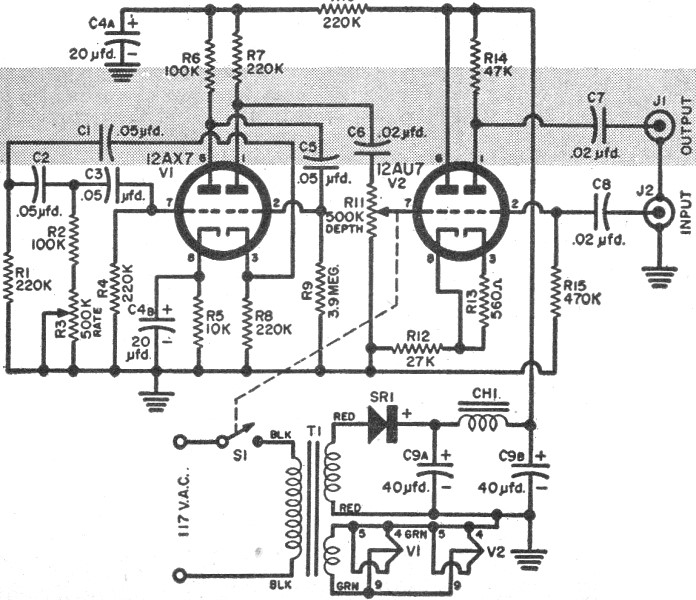
RF Cafe visitor Jim L. requested that this "Build Your Own Vibrato" article from the December 1957 edition of Popular Electronics be posted. The tagline states, "Make like Elvis with an electronic throbbing guitar." Vibrato, for those unfamiliar with...

This transmitter utilizes a 741 operational amplifier as a high-gain audio amplifier, which is activated by a microphone. The output of the 741 is connected to Q1, functioning as the driver for an LED. Potentiometer R1 serves as the...