
car subwoofer filter using op

The circuit utilizes the TL072 operational amplifier, which is known for its low noise and high slew rate, making it suitable for audio applications. The configuration of IC1A as a buffer serves to isolate the audio source from the load, ensuring that the signal integrity is maintained while preventing loading effects that could distort the audio signal.
The DPDT switch S1 allows the user to select between different configurations, thus enabling the subwoofer to be in phase with the other speakers in the system. This feature is crucial for achieving optimal sound quality and coherence in multi-speaker setups, particularly in automotive environments where space and acoustics can be challenging.
The low-pass filter formed by IC1B is essential for allowing only the desired bass frequencies to pass through to the subwoofer, effectively blocking higher frequencies that could lead to distortion. The adjustable pass frequency, controlled by the dual gang potentiometer R13, provides flexibility in tuning the filter to suit different musical genres or personal preferences, enhancing the listening experience.
The use of potentiometer R7 for level control allows the user to adjust the output level of the subwoofer, ensuring that it blends well with the rest of the audio system. This feature is particularly important in car audio systems, where cabin acoustics can vary significantly, and the balance between bass and other frequencies must be carefully managed.
Overall, this subwoofer filter circuit is a practical solution for enhancing the low-frequency performance of car audio systems, providing users with the ability to customize their sound experience effectively.Here is the circuit diagram of simple and easy subwoofer filter which will be operated from a 12V DC supply. Such a circuit is incredibly helpful in Car subwoofer applications. The circuit is nothing however a low pass filter whose pass frequency will be adjusted between 60 to 160 Hz.
The circuit is intended round the TL072 twin BIFET opamp IC. Ou t of the 2 opamps within the chip, IC1A is wired as a buffer. The left and right audio inputs when mixing is fed to the input of the IC1A using the DPDT switch S1. Switch S1 is that the section control switch which might be used to create the subwoofer in section with different speakers.
When S1 is in position {2, 180 degree phase shift are induced. POT R7 will be used for controlling the level. IC1B forms the low pass filter whose pass frequency will be controlled by adjusting the twin gang POT R13. 🔗 External reference
Related Circuits
Due to their speed, accuracy, effectiveness, and cost-efficiency, infrared (IR) digital thermometers have supplanted traditional mercury thermometers. An ear digital thermometer utilizes a thermopile sensor to measure the infrared heat emitted by the eardrum, which correlates with the temperature...
A circuit has been constructed based on a design from Silicon Chip magazine to test bipolar stepper motor collections. The circuit is easy to build and functions effectively. The described circuit is designed to facilitate the testing of bipolar stepper...
This is a computer I built for my car, its an MP3 music system but can also do other tasks. Based around a super-small sub-micro ATX motherboard from a computer known as the BookPC BKi810, I have put the...
One of the EL34 output valves had blown, and the normally silver-colored getter had turned completely white. Upon opening the amplifier, remnants of a trimpot, including some melted solder, were found on the bottom cover. The trimpot's value was...
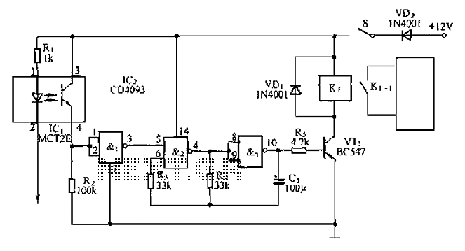
An anti-theft car audio system circuit is depicted, powered by a 12V DC supply from the car battery. Upon closing switch S1, the light-emitting diode in optocoupler IC1 activates, causing the phototransistor to conduct. This results in a high-level...
This article is intended for individuals interested in constructing their own car amplifier. The fundamental calculations involved will be discussed below. Understanding these concepts will enable the construction of a car amplifier independently. The complexity of designing a car...