
Carrier-current-am-receiver
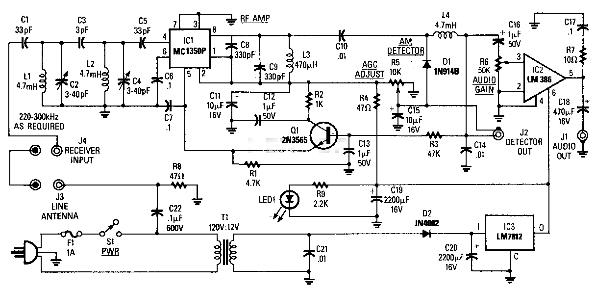
The AM Tuned Radio Frequency (TRF) receiver has a sensitivity of approximately 1 mV at the input for an audio output of 1/2 W. Capacitor C22 couples audio signals from the power line to the PC board and must be rated at 600 Vdc. Resistor R8 will cause fuse F1 to blow if C22 shorts. The signal from C22 is directed to a tuned network consisting of capacitors C1 through C5 and inductors L1 and L2, which has a bandwidth of 20 kHz, allowing only the desired signal to pass through. Integrated circuit IC1 serves as a gain block intermediate frequency (IF) chip with automatic gain control (AGC) capability and approximately 60 dB of gain. Components C8, C9, and L3, placed across the output of IC1, are broadly resonant around 280 kHz. Capacitor C10 couples radio frequency (RF) to detector diode D1, which functions as an envelope detector. The output from the detector is taken from capacitor C14, which sets the upper frequency limit at approximately 10 kHz. By reducing the value of C14, a higher frequency response can be achieved. The detector output is connected to an external jack. Audio components are routed to audio gain control R6, through capacitor C16 to IC2, an audio amplifier. Capacitor C18 couples up to 1/2 watt of audio to an external speaker. The kit is available from North Country Radio, P.O. Box 53, Wykagyl Station, NY 10804.
The AM Tuned Radio Frequency (TRF) receiver circuit is designed to receive amplitude modulated (AM) signals with a high degree of sensitivity and fidelity. The initial stage involves signal coupling through capacitor C22, which must withstand high voltage (600 Vdc) to ensure reliability. If C22 were to short, resistor R8 acts as a protective measure by blowing fuse F1, thereby preventing damage to the circuit.
The tuned network, comprising capacitors C1 to C5 and inductors L1 and L2, is critical for signal selection, providing a narrow bandwidth of 20 kHz that filters out unwanted frequencies while allowing the desired signal to pass. This is essential for effective AM reception, where adjacent channel interference can be a significant issue.
Integrated circuit IC1 functions as an intermediate frequency (IF) amplifier, providing a substantial gain of approximately 60 dB, which is essential for amplifying weak signals received by the antenna. The automatic gain control (AGC) feature of IC1 ensures consistent audio output levels despite variations in signal strength.
The output stage of IC1 is enhanced by the resonant components C8, C9, and L3, which are tuned to resonate around 280 kHz, optimizing the amplification of the desired frequency range. Following amplification, capacitor C10 couples the RF signal to detector diode D1, which demodulates the AM signal to retrieve the audio information.
The envelope detector output, accessed through capacitor C14, is critical for setting the upper frequency limit of the audio output, typically around 10 kHz. Adjustments to the value of C14 can allow the circuit to accommodate higher frequency responses if desired. The audio output is then routed to an external jack for further processing or amplification.
The audio signal is fed through audio gain control resistor R6, allowing for user adjustment of the output level before it reaches the audio amplifier IC2. Capacitor C16 facilitates the coupling of the audio signal to IC2, which amplifies the audio to a level suitable for driving an external speaker. The final output stage, represented by capacitor C18, ensures that the audio signal can deliver up to 1/2 watt of power to the speaker, providing adequate volume for a variety of listening environments.
This comprehensive design allows for a robust and user-friendly AM radio receiver, suitable for hobbyists and audio enthusiasts alike, available through North Country Radio.The AM Tuned Radio Frequency (TRF) receiver, has a sensitivity of about 1 m V at tbe input for an audio output of "iz W. Capacitor C22 couples audio signals from the power line to the PC board-it must be rated at 600 Vdc.
R8 will cause F1 to blow, if C22 shorts. The signal from C22 goes to a tuned network (C1 through C5, Ll, and L2) that has a 20-kHz bandwidth, which allows only the desired signal to pass through. IC1 is a gain block i-f chip that has AGC capability and approximately 60 dB of gain. Components C8, C9, and L3, which are placed across tbe output of IC1, are broadly resonant around 280kHz.
C10 couples rf to detector -diode D 1, which is used as an envelope detector. The detector output is taken from C14, which sets the upper frequency limit at about 10kHz or so. By reducing tbe value of C14, high frequency response can be obtained. The detector output is connected to an external jack. Audio components are fed to audio-gain control R6, through C16 to IC2, an audio amplifier. C18 couples up to 1/z watt of audio to an external speaker. The kit is available from North Country Radio, P.O. Box 53, Wykagyl Station, NY 10804. 🔗 External reference