
Cars Basic Heavy Duty Electrical System

The heavy-duty electrical system circuit schematic is designed to provide reliable power management for automotive or industrial applications. The primary components include a battery, which serves as the main power source, supplying voltage to the system. The starting motor is responsible for initiating the engine's operation, drawing current from the battery when engaged.
The alternator plays a crucial role in recharging the battery while the engine is running, converting mechanical energy into electrical energy and maintaining the system's voltage. The magnetic switch, often referred to as a solenoid, acts as a relay that controls the flow of current to the starting motor, allowing for safe and efficient engine start-up. The ignition switch is utilized to control the power supply to the entire system, enabling or disabling the electrical circuit as necessary.
Wiring is an integral part of the circuit, facilitating connections between these components. Proper gauge and insulation of wires are essential to handle the current load and prevent overheating. The schematic should include clear indications of the wiring paths, connection points, and any necessary fuses or circuit breakers to protect the system from overloads.
Overall, the circuit is designed to ensure that all components function harmoniously, providing a robust solution for starting and operating heavy-duty machinery or vehicles efficiently.A circuit schemes basic heavy-duty electrical system which connecting components such battery, starting motor, alternator, magnetic switch, ignition switch, and connected wiring 🔗 External reference
Related Circuits
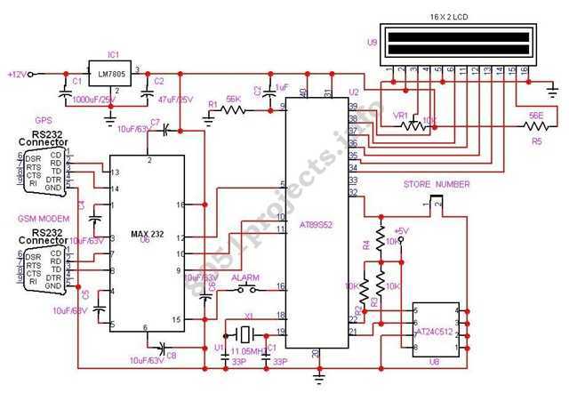
In this project AT89S52 microcontroller is used for interfacing to various hardware peripherals. The current design is an embedded application, which will continuously monitor a moving Vehicle and report the status of the Vehicle on demand. For doing so...
A Transcutaneous Electrical Nerve Stimulation (TENS) device is essentially a machine that delivers electric shocks. This device was prescribed on a loan basis by an orthopedic specialist. The unit features numerous programs, although only one was utilized. Measurement of...

The design of solar panel systems with a lead-acid buffer battery is typically configured to ensure that the battery remains charged even during periods of limited sunlight. Solar panel systems integrated with lead-acid buffer batteries are designed to optimize energy...
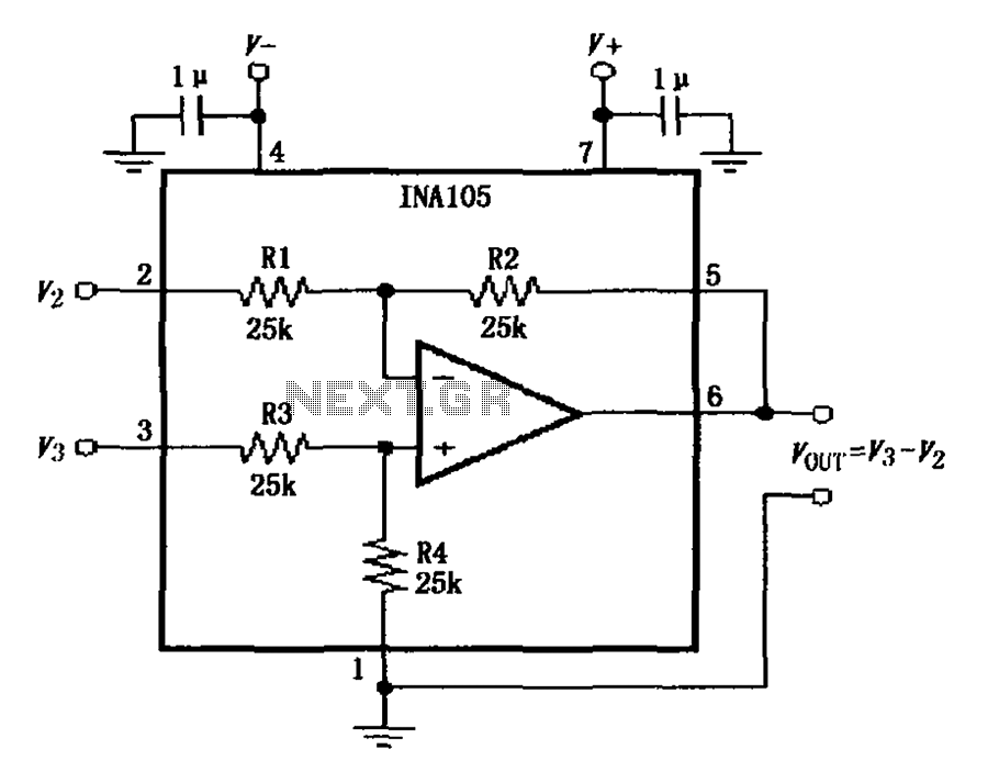
The power supply terminal should utilize a 1 µF chip capacitor filter, positioned as close as possible to the chip's supply pin. The signal is generated by the input pins 2 and 3. The source resistance of the signal...
.png)
Have you ever considered implementing your own home security alarm system? It is one of the simplest and most interesting circuits for electronics beginners. The new home security equipment utilizes a Light Dependent Resistor (LDR) to detect security breaches....
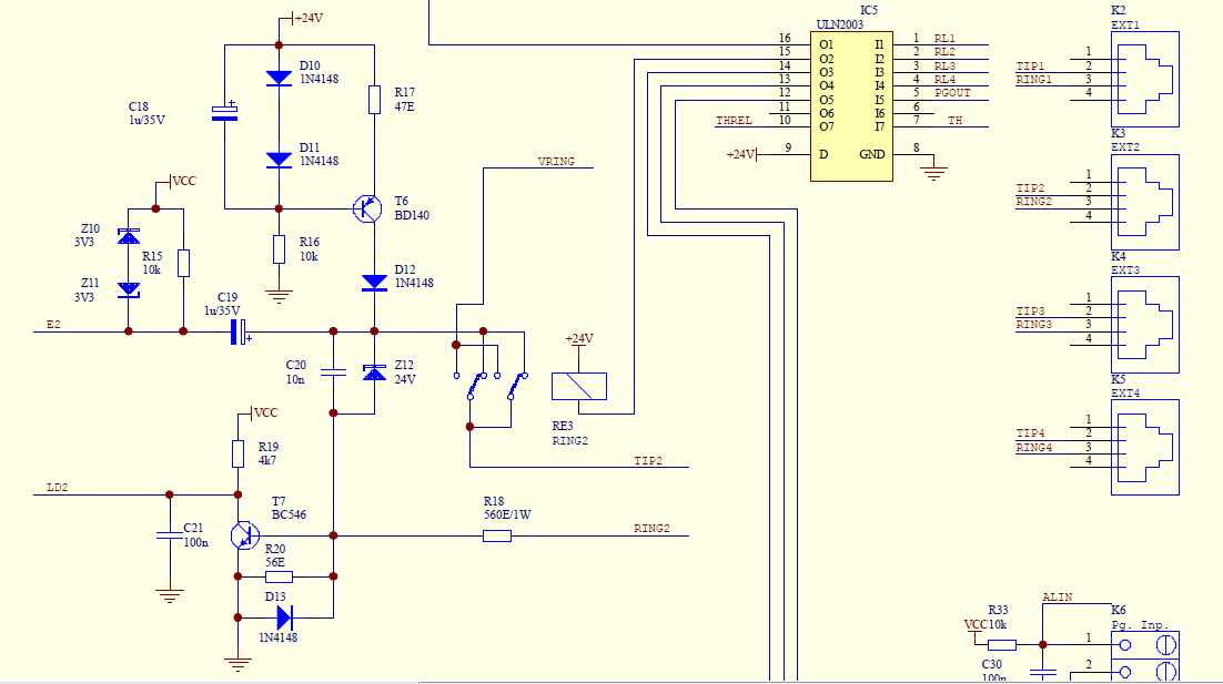
Create a simple telephone-based intercom system in a new house. Shouting between rooms is not effective, and using an instant messaging client or FaceTime lacks the immediacy of a voice call. A collection of old wired telephones is available...