
Cellular Phone Detector

The circuit operates by utilizing a sensor coil (L1) that is sensitive to the electromagnetic field generated by the cellular phone during an incoming call. This coil is designed to be placed in proximity to the phone, allowing it to pick up the weak signals emitted by the device's receiver. Upon detecting these signals, the coil generates a small voltage that is fed into the base of transistor Q1. The transistor acts as an amplifier, increasing the signal strength to a level sufficient for further processing.
Transistor Q1 is configured in a common-emitter arrangement, which not only amplifies the incoming signal but also provides the necessary current to drive the subsequent components. The amplified signal is then directed to the input pin of a monostable multivibrator IC (IC1), which is responsible for generating a timed output pulse. This output pulse is crucial for controlling the LED's flashing behavior.
To ensure that the LED receives adequate voltage for optimal brightness, the output from IC1 is processed through a voltage-doubling circuit consisting of capacitor C2 and diode D2. This configuration effectively doubles the output voltage from the monostable multivibrator, thus allowing the ultra-bright LED to operate at its required peak voltage. The use of high-efficiency LEDs ensures that the circuit remains power-efficient while providing a visually striking indication of an incoming call.
Overall, this circuit is a practical solution for users who wish to be alerted of incoming calls without relying on the phone's ringer, making it particularly useful in situations where silence is necessary.This circuit was designed to detect when a call is incoming in a cellular phone (even when the calling tone of the device is switched-off) by means of a flashing LED. The device must be placed a few centimeters from the cellular phone, so its sensor coil L1 can detect the field emitted by the phone receiver during an incoming call.
The signal detected by the sensor coil is amplified by transistor Q1 and drives the monostable input pin of IC1. The IC`s output voltage is doubled by C2 & D2 in order to drive the high-efficiency ultra-bright LED at a suitable peak-voltage.
N 🔗 External reference
Related Circuits

A long time ago, when telephones were simple and reliable from an electrical standpoint, telecom operators installed surge protection on all telephone lines at risk from storms. Paradoxically, as modern technology has led to the use of delicate and...
The microphone preamplifier circuit design presented in this schematic utilizes the SSM2015 component manufactured by Precision Monolithics Inc. (PMI). This component provides high amplification with low noise characteristics (1.3nV/f). The design is configured to handle differential input signals and...
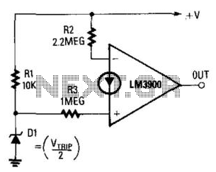
The output becomes high when the supply voltage drops below a threshold set by the zener diode D1. If D1 is a 5.6-V zener diode, the operational amplifier will activate when the supply voltage decreases to around 11 V....

A battery-operated ionization chamber smoke detector features a circuit designed to generate a distinct alarm when the battery approaches the end of its useful life. The circuit employs the MCMOS MC14572 integrated circuit for two alarm oscillators, one for...

While conversing with a distant subscriber on the telephone, it is common to experience frustration due to faint audio that is barely intelligible. To address this issue, an inexpensive amplifier circuit is proposed. This circuit can be easily assembled...

This simple FM wireless microphone transmitter can transmit speech over a short range. It can be used as a simple cordless microphone. The circuit uses two. The FM wireless microphone transmitter is designed for short-range audio transmission, making it suitable...