
CGA to SCART Adapter

The CGA to SCART adapter circuit is designed to accommodate the video signal conversion requirements between CGA (Color Graphics Adapter) and SCART (Syndicat des Constructeurs d'Appareils Radiorécepteurs et de Télévision) standards. The circuit primarily utilizes resistive voltage dividers to adjust the signal levels appropriately. The resistors R4, R5, and R6 are crucial in transforming the TTL-level signals from the CGA output to the required SCART levels, ensuring compatibility with the SCART input specifications.
The impedance matching is addressed through the configuration of these resistors, which, while not achieving an exact 75-ohm output, maintain signal integrity sufficiently for practical applications. The use of R1, R2, and R3 serves to modulate the brightness of the output signal, allowing for dynamic adjustment based on the state of pin 6. This feature enhances the adaptability of the adapter in various display scenarios, particularly when dealing with older CRT televisions that may not handle high brightness levels well.
Moreover, the synchronization aspect of the video signal is critical for proper display functionality. The circuit employs resistors R7 to R11 in conjunction with transistor T1 to combine the horizontal and vertical sync pulses from the CGA board, creating a composite sync signal. This signal is essential for synchronizing the display output with the video signal, ensuring that the image is rendered correctly on SCART-compatible televisions.
In summary, the CGA to SCART adapter is a compact and efficient solution for interfacing CGA video signals with SCART inputs, effectively managing signal levels, impedance, and synchronization to deliver a functional output suitable for a variety of display devices. The design emphasizes simplicity and effectiveness, making it an ideal choice for retro gaming and vintage computer applications.CGA to SCART adapter has great advantages as it does not require separate power source and that uses very few external components, which can be easily adapted in the SCART connector. The signals from R, G and B pins of the CGA`s board are converted from TTL levels to SCART levels with resistors R4, R5 and R6 and entry`s impedance (75 ©) of scart
inputs. Output Impedance of voltage dividers thus created is not exactly 75 © as specified for SCART inputs, but in practice the behavior seems to result not big differences. R1-R3 resistors from pin 6 of the CGA`s entrance and pins R, G and B of the SCART connector ensure reduction of 50% of brightness when pin 6 active.
From synchronization pulses on horizontal and vertical of CGA board it creates, with the help of R7-R11 ²s and T1, a composite signal timing (SYNC) and a signal remission for TV. 🔗 External reference
Related Circuits
This circuit provides a short circuit protected power supply from PC 12V supply voltage. This is particularly handy when working with PC interfacing projects. More: Fig-1 shows the circuit diagram of the complete power supply. The necessary 12V supply...
Video signals can be challenging to display on an oscilloscope. Standard trigger circuits in most oscilloscopes often struggle to achieve a stable trigger from the combined vertical and horizontal sync signals, color burst, and picture signal found in a...
The EEprom programmer software supports the following devices 28C16, 28C256, 28C17, 29C256, 28C64. Diode D1 and resistor R1 provide the VDD isolation when programming the 24 pin devices. The jumper J3 must be shorted for 24 pin devices, and...
An AC-DC converter known for its accuracy is the SMPS AC-DC converter. Test data indicates an efficiency of 85.4% at a 230 Vac input with a 6A output current, and 83.2% at a 115 Vac input with the same...
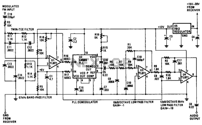
The operational amplifier (Op Amp) U1 and its associated components form a 67-kHz bandpass filter. A twin-T network, consisting of four 1100-ohm resistors and four 0.0022-microfarad capacitors, is integrated into the feedback loop of the op amp. This configuration...
The device shows a voltage of 24V at no load on pins +4, 5 and -7, 8. This configuration is referred to as a passive power injector. When a current draw of 1A was attempted from the device, it...