
Cheap DC Voltage Doubler Circuit

The circuit operates on the principle of voltage doubling through capacitive charge and discharge cycles, utilizing an oscillator to create an alternating waveform. The essential components of the circuit include two capacitors, two diodes, and an oscillator circuit, which can be implemented using a simple transistor or a dedicated oscillator IC.
The first stage of the circuit involves the oscillator generating a square wave signal, which alternates between high and low states. During the positive cycle of this waveform, the first diode becomes forward-biased, allowing current to flow from the 5V supply through the first capacitor, charging it to approximately 5V. Simultaneously, the second diode remains reverse-biased, preventing current from flowing back to the power supply.
In the negative cycle, the first diode becomes reverse-biased, while the second diode becomes forward-biased. This action allows the charge stored in the first capacitor to be added to the 5V supply voltage, effectively doubling the voltage across the second capacitor to approximately 10V. The second capacitor then holds this voltage, which can be used to power other components or circuits requiring a higher voltage.
It is important to consider the load that will be connected to the output of the voltage doubler, as the output voltage may sag under heavy loads. Additionally, the choice of diodes should be made carefully; they should have a low forward voltage drop and be rated for the expected current and reverse voltage to ensure reliable operation. Capacitors should also be rated appropriately for voltage and capacitance to minimize ripple and support the desired load conditions.
Overall, this DC voltage doubler circuit is a cost-effective solution for applications requiring a higher voltage from a lower voltage power source, making it suitable for various electronic projects and devices.This is a cheap DC Voltage Doubler Circuit diagram, which requires a few components and will deliver 10V from a 5V power supply. If the oscillator must be.. 🔗 External reference
Related Circuits
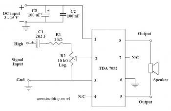
This is an audio amplifier circuit that uses the TDA7052 as the main component, along with five additional components to support its operation. The ideal supply voltage for this circuit is approximately 6-12V, and it does not require a...

This filter circuit, which utilizes the LM1458 or a similar operational amplifier, has a frequency response ranging from 300 Hz to 3.4 kHz, exhibiting a roll-off of 12 dB per octave outside the passband. Section A serves as the...
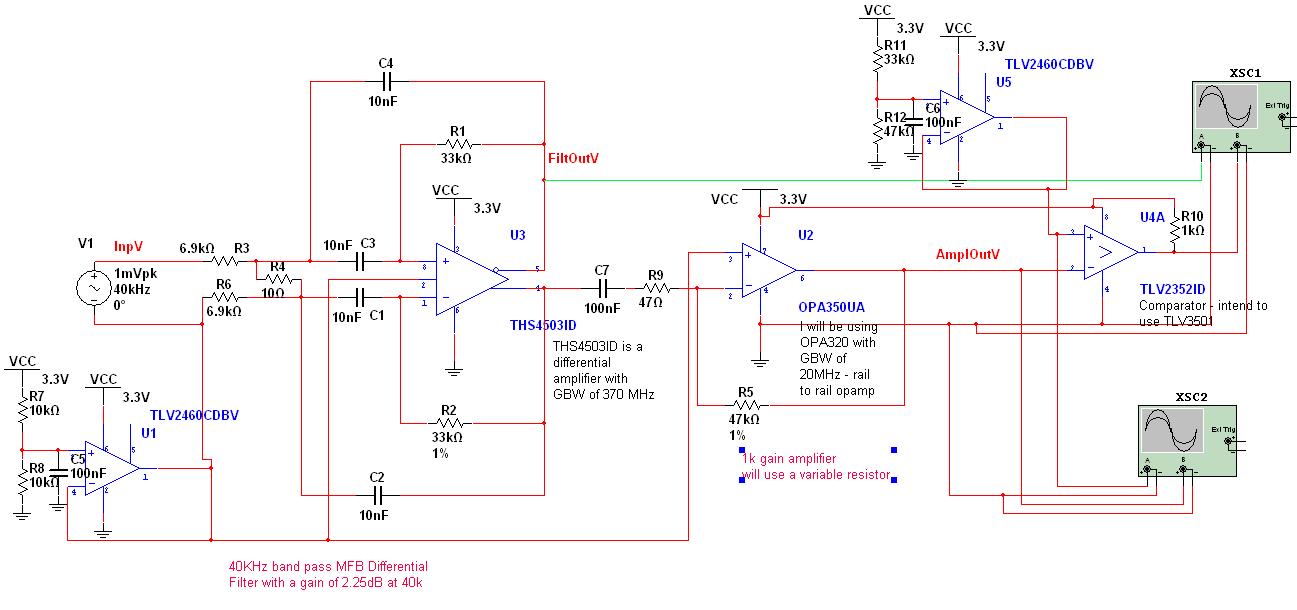
A circuit has been designed to detect the duration of an ultrasonic pulse as it travels a certain distance. The input signal is sourced from a 40 kHz ultrasonic receiver. The first stage consists of a 40 kHz band-pass...
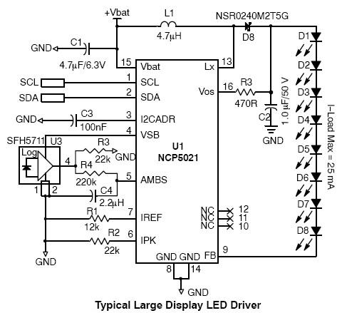
This high-voltage white LED driver electronic circuit schematic utilizes the NCP5021 integrated circuit from On Semiconductor. The NCP5021 is designed with an ambient light sensing feature and can drive up to eight LEDs in series for portable backlight applications....
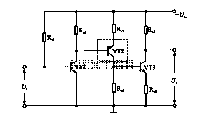
A multi-stage DC-coupled amplifier circuit utilizes NPN type transistors. Each stage is designed to achieve an appropriate operating point at the base, resulting in a stepwise increase in collector potential, which subsequently reduces the final output voltage range. To...
This design circuit is for a mass air flow (MAF) sensor. The MAF sensor converts the volume of air entering the engine into a voltage signal. The main components of the MAF sensor include a thermistor, a platinum hot...