
cheap frequency counter

The described frequency counter circuit is designed to provide a cost-effective solution for frequency measurement by leveraging the capabilities of a digital multimeter. The core component of the circuit is the frequency-to-voltage converter, which translates frequency signals into corresponding voltage levels that can be easily read by the DMM.
In position A, the converter is configured to measure frequencies from 10 Hz to 1 kHz. The output sensitivity of 35 mVpp allows for accurate readings at lower frequencies, ensuring that even small signal variations can be detected. The DMM is connected to the output terminals of the converter, where it interprets the voltage levels as frequency values. The linear relationship established in this range means that a frequency of 1 kHz will yield an output voltage of 1 V, facilitating straightforward calculations and readings.
In position B, the frequency range extends from 1 kHz to 100 kHz, where the sensitivity increases to 350 mVpp. This increase in sensitivity at higher frequencies ensures that the DMM can accurately measure rapid changes in frequency. The conversion ratio remains consistent, with 100 kHz corresponding to an output of 1 V, allowing users to switch seamlessly between frequency ranges without recalibration.
The design emphasizes ease of use and integration, as the high input impedance of the DMM minimizes loading effects on the circuit. This characteristic is crucial for maintaining the integrity of the frequency signal being measured. Overall, this frequency counter circuit represents an efficient and economical approach to frequency measurement, suitable for various applications where precision and cost-effectiveness are paramount.This frequency counter uses your existing digital multimeter as the display unit that is why it can be constructed at very low cost. Due to the high impedance of most DMMs, a frequency to voltage converter can be easily connected to it without matching problems.
The converter shown in the diagram has a frequency range of 10 Hz up to 1 kHz (positio n A) and 1 kHz up to 100 kHz (position B). The sensitivity at low frequencies 10 Hz up to 1 kHz is around 35 mVpp and increases to 350 mVpp at a frequency of 100 kHz. The DVM you are going to use must be connected to the plus and minus terminals of the converter`s output.
The conversion in A range is 1 kHz= 1V and in B range is 100 kHz= 1V. 🔗 External reference
Related Circuits
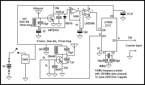
This is basically the frequency meter section of the frequency meter/pulse generator based on the AT90S2313 described elsewhere on this site, combined with the 100 MHz RF interface described in the page about the RS-232 to 100 MHz RF...
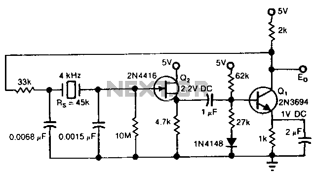
The Pierce circuit oscillates at 4 kHz. At low frequencies, the crystal's internal series resistance Rs is quite high (45 kΩ at 4 kHz). Therefore, an FET-based source follower is included to prevent Q1 from loading the crystal output. The...
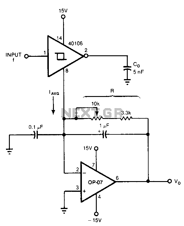
Six components can configure a circuit whose output voltage is proportional to its input frequency. The average current from the ground pin 8 of the 40106 Schmitt trigger inverter is linearly dependent on the frequency at which the capacitor...
A more affordable method to create or purchase a device that offers similar functionality. It does not necessarily need to be remote-controlled if it can be programmed to activate at specific times. This description suggests the development of a cost-effective...
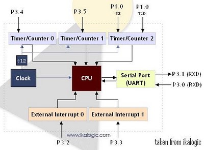
The diagram below illustrates a simplified representation of the main peripherals present in the 89S52 microcontroller, which is part of the 8052/8051 family. The 89S52 includes three Timers/Counters. The term "Timer/Counter" is applicable because this unit can function either...
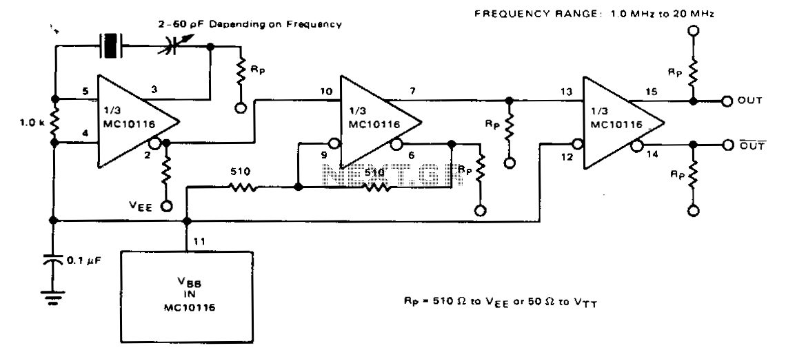
For frequencies below 20 MHz, a fundamental-frequency crystal can be utilized, eliminating the need for a resonant tank. At these lower frequencies, the typical MECL 10,000 propagation delay of 2 ns becomes negligible compared to the oscillation period, necessitating...