
Cheap siren with nand gate IC

The siren sound generator circuit is designed to produce an audible alarm or warning signal, making it suitable for various applications such as security systems, automotive alerts, or novelty sound effects. The core component of this circuit is the CD4011 integrated circuit, which comprises four independent two-input NAND gates.
In this configuration, the NAND gates are arranged to create an oscillator circuit. By connecting the output of one NAND gate back to its inputs, a feedback loop is formed, allowing the circuit to oscillate. The frequency of oscillation can be adjusted by varying the resistor and capacitor values connected to the circuit, which directly influences the timing characteristics of the oscillation.
The output of the oscillator can be fed into a simple audio amplifier circuit to drive a speaker or piezo buzzer, producing the siren sound. Additional components, such as resistors and capacitors, may be employed to shape the sound wave, providing different tones or patterns that can mimic a siren or alarm.
Overall, this siren sound generator circuit is a straightforward yet effective solution for generating sound alerts, leveraging the capabilities of the CD4011 NAND gate IC to create versatile audio signals.This is a siren sound generator circuit. Which is less expensive and can create simple. The IC1 is using CD4011 (Digital Nand Gate) and the IC2 is.. 🔗 External reference
Related Circuits
Although modern electrical appliances are increasingly self-powered, particularly portable devices used during camping or summer vacations, there are still occasions when a 230 V AC source is necessary. Additionally, it is beneficial for this source to operate at a...

Using just two NAND or inverter gates, it is possible to build a D-type (or toggle) flip-flop with a push-button input. At power-up, the output of gate N2 is at a logical 1, ensuring that transistor T2 is switched...
The 555 timer on the right is configured as an alarm sound generator, while the second 555 timer on the left operates as a 1 Hz astable multivibrator. The output from the left timer modulates the frequency of the...
This small transistor tester employs a simple visual indication system to perform a quick go/no-go check on both NPN and PNP transistors. When testing a functioning NPN transistor, the green LED (D1) will flash, while the red LED will...
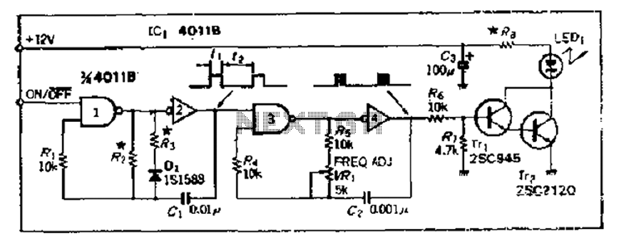
The 4000 Series 4011B is a NAND gate used in conjunction with a 4AI NAND gate circuit group to create two loops of an unstable multivibrator. The first NAND gate and the second NAND gate operate at approximately 1...
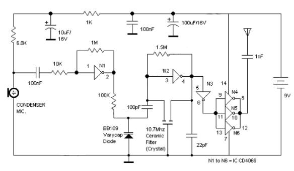
Logic Gates FM Transmitter Circuit Electronic Circuit Schematic Wiring Diagram. The FM transmitter circuit utilizing logic gates is a fundamental electronic design that operates by modulating a carrier frequency with an audio signal. This circuit typically consists of various logic...