
Christmas light circuit

The Christmas lights circuit leverages the CD4069 CMOS hex inverter, which is a versatile component known for its ability to perform logical inversion while consuming minimal power. In this application, it serves as a control unit for the LED circuits, allowing for the modulation of light patterns and effects.
The four circuits, each comprising 50 LEDs, are connected in parallel to ensure uniform brightness and distribution of voltage across the LEDs. The LEDs are selected for their efficiency and longevity, making them ideal for decorative applications such as Christmas lighting.
The direct connection to a 220V AC power source eliminates the need for a transformer, simplifying the design and reducing costs. However, this necessitates the use of a bridge rectifier, which converts the AC voltage to a pulsating DC voltage suitable for powering the LEDs. The bridge rectifier consists of four diodes (VD1 to VD4) arranged in a configuration that allows for the conversion of both halves of the AC waveform into a usable DC output.
To stabilize the voltage and reduce ripple in the rectified output, resistors R1 and R5 are employed to manage differential pressure within the circuit. These resistors help to limit the current flowing through the LEDs, preventing damage from excessive current while also ensuring that the LEDs operate within their specified voltage range.
Capacitor C1 plays a critical role in filtering the rectified output. It smooths the pulsating DC voltage by charging and discharging, thereby reducing voltage fluctuations and providing a more stable power supply to the LED circuits. This filtering is essential for maintaining consistent brightness and preventing flickering in the LED lights.
Overall, this Christmas lights circuit design exemplifies a practical approach to creating an efficient and visually appealing lighting solution, utilizing readily available components and straightforward circuitry to achieve the desired effects.The chart shows the Christmas lights circuit which uses simple, inexpensive CD4069 CMOS hex inverter to control four circuits with 200 light-emitting diodes (each circuit has 50 LEDs), and it is directly supplied by the 220V power source without power transformer. The power is bridge rectified by VD1 ~ VD4, differential pressured by R1, R5 and filtered by C1.. 🔗 External reference
Related Circuits

The schematic for this project is not overly complex; however, it is crucial to understand the circuit board and its operation due to the high voltages generated. Below is a rough draft schematic of the camera used for this...

A capacitive proximity controller typically consists of a radio frequency oscillation circuit and a detection plate. The circuit is constructed using discrete components for capacitive proximity sensing detection. The transistor VT1, along with surrounding components, forms a radio frequency...

A telephone utilizes electric current to transmit sound information between homes. During a conversation, a steady electric current flows through both telephones, which share this current. As one person speaks into their telephone's microphone, the current drawn from the...

The circuit illustrated in Figure 3-136 incorporates a limit switch (SQ) that, when the motor operates a mechanical device to reach a predetermined position, cuts off the power and initiates dynamic braking for fast and accurate positioning. This configuration...

The circuit illustrated in Figure 3-56 features both manual and automatic start-up modes. It incorporates two relays, KA2 and KA3, within the control loop. The circuit design ensures that KM1 is cut off before and after activating KM2. A...
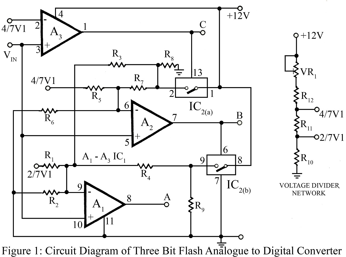
The flash type converter is the simplest and fastest type of analog-to-digital converter. The entire digital output word is available immediately after the propagation delay time of the comparators and the encoding logic gates. A typical conversion time for...