
Circuit Project: Sound Activated Switch II

The sound-activated switch operates by detecting specific sound frequencies or patterns, typically using a microphone or a sound sensor. Upon receiving a sound signal that meets predefined criteria, the switch activates an output device, such as a light or motor. This functionality is particularly advantageous in scenarios where hands-free operation is desired, enhancing convenience and accessibility.
The circuit generally consists of several key components: a microphone or sound sensor, an amplifier to boost the audio signal, a microcontroller or comparator to process the sound input, and a relay or transistor to control the output device. The microphone captures ambient sound, and the amplifier increases the signal strength for better detection. The microcontroller is programmed to recognize specific sound patterns, triggering a high or low output signal based on the detection. This output then activates the relay or transistor, allowing current to flow to the connected device, thereby enabling it to perform the desired action.
For home automation, this technology can be integrated into various systems, such as lighting control, alarm systems, or even as a trigger for smart home devices. The sound-activated switch can be customized to respond to different sounds, making it versatile for various applications. Additionally, the circuit can be designed to include features such as adjustable sensitivity, which allows users to set the threshold for sound detection according to their environment.
Overall, the sound-activated switch represents an innovative approach to control mechanisms, leveraging audio signals for practical applications in both robotics and home automation.With this sound activated switch, control by sound may be very useful, not just on a robot but also for a bit of home automation, for example a sound-acti.. 🔗 External reference
Related Circuits
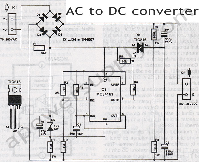
The following circuit diagram depicts a variable power supply controlled by a PIC microcontroller. An LCD display is utilized to show the actual output current and voltage values. This digital power supply incorporates a push-button switch to adjust the...
This voltage-to-frequency converter circuit features a voltage-controlled oscillator with a deviation of 0.5%. The integrated circuit IC1 functions as a multivibrator, generating rectangular impulses of equal width. The output frequency is adjustable via the U1 voltage. The D3 diode...
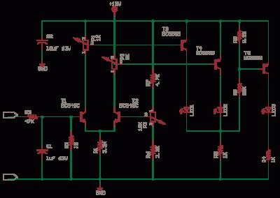
This is a constant current source using a FET. It serves as a simple replacement for a series resistor to limit current. The N-Channel FET BF256C can provide a current of 15mA. Before using integrated circuits, it is advisable...

The Saver V5.0 operates a simple clock emulation program that controls a night light to turn on and off at preset times, specifically from 19:00 to 22:00 daily. This design is characterized by its low cost, easy installation, lack...

FIG M is a variable speed motor control for the opening and closing of a wicket gate. It features an electric governor. The system is activated by a power switch (SA) located on the front grid, and a toggle...
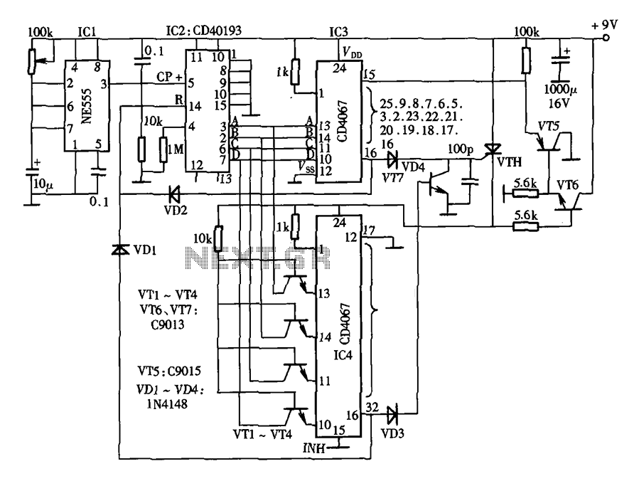
The lantern control circuit allows for the management of 30 outputs through an external driver circuit, specifically designed for water sports or large decorative lantern applications. The circuit features a control pulse generator, which regulates the lights, and an...