


BJT H-bridge Circuit Details
#BJT
#H-bridge
#opto-isolator
#microprocessor
#motor driver
#forward control
#reverse control
#enable control
#BASIC stamp
#68HC11
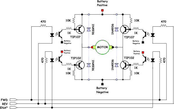
Description: The opto-isolator LEDs are connected to three wires labeled "FWD," "REV," and "ENA." These wires serve as the interface between the bridge and the microprocessor. It is important to note that there is no "ground" signal present. When connecting these pins to a BASIC Stamp, 68HC11, or similar microcontroller, various combinations of 1's and 0's on the lines activate different pairs of transistors. The processor pins provide a connection to ground when outputting a logic 0. For instance, when FWD is set to 1 and ENA is set to 0, the lower right sink receives current from FWD and returns it through the ENA-connected pin. At all times, the pin must supply enough current to activate two LEDs and, when set to zero, sink the current from both LEDs. With 560-ohm resistors and a 5V processor like the PIC, this is manageable. According to the opto-isolator datasheet, each LED has a forward voltage drop of 1.2V, resulting in a current of approximately 6.8mA per LED, totaling 14mA of load. The PIC can drive up to 20mA. Replacing the 560-ohm resistors with 680-ohm resistors can further reduce the current through the LEDs. However, with a forward voltage drop of up to 1.4V and a minimum PIC operating voltage of 4.5V, using 680-ohm resistors would yield only 4.5mA per LED, which is below the 5mA specified in the datasheet. Therefore, the 560-ohm resistor is the more suitable option, providing adequate margin. This interface design allows access to all the useful combinations of sinks and sources while preventing "illegal" states. An illegal state in a full quadrant H-bridge (four inputs, one for each quadrant) occurs when both the upper source and lower sink on the same side are activated, resulting in a direct short circuit between the battery terminals, which can damage the transistors. Additionally, low-end PIC chips, such as the PIC16F628, feature a single hardware PWM line, enabling connection to the bridge and a couple of GPIO pins for the FWD and REV lines, facilitating hardware PWM on the bridge. It is advised not to exceed 2.5kHz unless a faster opto-isolator is utilized. Prior to final assembly, it is essential to analyze the design to characterize its performance, ensuring that the H-bridge meets the required specifications and functions as intended.
The circuit utilizes an H-bridge configuration to control the direction and speed of a motor. The FWD, REV, and ENA lines are essential for interfacing with a microcontroller, allowing for precise control over the motor's operation. The absence of a direct ground connection in the interface design is intentional, as it prevents potential short circuits that could occur if both the high-side and low-side transistors were activated simultaneously.
The choice of 560-ohm resistors is critical, as they ensure that the current flowing through the opto-isolator LEDs remains within safe limits while allowing sufficient current to activate the LEDs effectively. The forward voltage drop of the LEDs must be taken into account when designing the circuit, as variations in LED characteristics can affect performance. The calculated current of 6.8mA per LED at a 5V supply voltage ensures that the opto-isolators operate reliably without exceeding the current ratings of the PIC microcontroller.
The use of PWM (Pulse Width Modulation) for motor control allows for efficient speed regulation. By connecting the PWM output from the PIC to the ENA line, the duty cycle can be varied, effectively controlling the power delivered to the motor. The recommendation to keep the PWM frequency below 2.5kHz is based on the response time of the opto-isolator, which could lead to performance issues if exceeded.
Overall, the design prioritizes both functionality and safety, providing a robust solution for motor control applications while minimizing the risk of component failure due to incorrect states in the H-bridge configuration. Proper analysis and testing of the circuit will ensure that it meets the required specifications and operates reliably in practical applications.You should notice that the opto-isolator LEDs are connected to three wires labeled "FWD", "REV", and "ENA*. " These wires deserve a bit of explanation. The FWD, REV, and ENA* lines are the interface between the bridge and the microprocessor. You will notice their is no "ground" signal. When you connect these pins to a BASIC stamp or a 68HC11 or what-ever, combinations of 1`s and 0`s on the line turn on different pairs of transistors. The following table lists all possible combinations of input. This works because the processor pins become a connection to ground when they are outputting a logic 0. Thus when FWD is 1 and ENA is 0, the lower right sink is getting current from FWD which it is returning through the pin connected to ENA.
At any given time the pin must be able to supply enough current to turn on two LEDs and when set to zero sink the current of two LEDs. With the 560 ohm resistors and a 5V processor like the PIC this is not a problem. From the data sheet on the opto-isolator, each LED has a forward voltage drop of 1. 2V, so (5 - 1. 2) / 560 is 6. 8mA per LED or 14mA of load total. The PIC is specified to be able to drive 20mA. You can replace the 560 ohm resistors with 680 ohm resistors to reduce the current through the LEDs still further.
However the LED voltage drop can be as high as 1. 4V and the PIC`s operating voltage can be as low as 4. 5V, in that condition with 680 ohm resistors you would only put 4. 5mA into each LED which is below the 5mA specified in the datasheet. The 560 ohm resistor is the better choice as it maintains sufficient margin. So why go to all this trouble The interface as designed gives you access to all of the interesting combinations of sinks and sources enable, while not allowing for any "illegal" states. An illegal state in a full quadrant H-bridge (4 inputs, one for each quadrant) is one that turns on the upper source and lower sink on the same side.
This combination causes a direct short circuit to be created between the battery terminals (not good!) and usually causes one or both of the transistors that are on to go up in smoke. Further, as the low end PIC chips like the PIC16F628 has a single hardware PWM line, this lets you connect that line to the bridge and a couple of GPIO pins to the FWD and REV lines to get a hardware PWM on the bridge.
Just remember not to go above 2. 5Khz unless you replace the opto-isolator with a faster one. So before we solder it all together, lets analyze the design and try to characterize its performance. This will give us confidence that this H-bridge will meet the requirements we need it to meet, and we won`t be surprised by it not working on us.
The circuit utilizes an H-bridge configuration to control the direction and speed of a motor. The FWD, REV, and ENA lines are essential for interfacing with a microcontroller, allowing for precise control over the motor's operation. The absence of a direct ground connection in the interface design is intentional, as it prevents potential short circuits that could occur if both the high-side and low-side transistors were activated simultaneously.
The choice of 560-ohm resistors is critical, as they ensure that the current flowing through the opto-isolator LEDs remains within safe limits while allowing sufficient current to activate the LEDs effectively. The forward voltage drop of the LEDs must be taken into account when designing the circuit, as variations in LED characteristics can affect performance. The calculated current of 6.8mA per LED at a 5V supply voltage ensures that the opto-isolators operate reliably without exceeding the current ratings of the PIC microcontroller.
The use of PWM (Pulse Width Modulation) for motor control allows for efficient speed regulation. By connecting the PWM output from the PIC to the ENA line, the duty cycle can be varied, effectively controlling the power delivered to the motor. The recommendation to keep the PWM frequency below 2.5kHz is based on the response time of the opto-isolator, which could lead to performance issues if exceeded.
Overall, the design prioritizes both functionality and safety, providing a robust solution for motor control applications while minimizing the risk of component failure due to incorrect states in the H-bridge configuration. Proper analysis and testing of the circuit will ensure that it meets the required specifications and operates reliably in practical applications.You should notice that the opto-isolator LEDs are connected to three wires labeled "FWD", "REV", and "ENA*. " These wires deserve a bit of explanation. The FWD, REV, and ENA* lines are the interface between the bridge and the microprocessor. You will notice their is no "ground" signal. When you connect these pins to a BASIC stamp or a 68HC11 or what-ever, combinations of 1`s and 0`s on the line turn on different pairs of transistors. The following table lists all possible combinations of input. This works because the processor pins become a connection to ground when they are outputting a logic 0. Thus when FWD is 1 and ENA is 0, the lower right sink is getting current from FWD which it is returning through the pin connected to ENA.
At any given time the pin must be able to supply enough current to turn on two LEDs and when set to zero sink the current of two LEDs. With the 560 ohm resistors and a 5V processor like the PIC this is not a problem. From the data sheet on the opto-isolator, each LED has a forward voltage drop of 1. 2V, so (5 - 1. 2) / 560 is 6. 8mA per LED or 14mA of load total. The PIC is specified to be able to drive 20mA. You can replace the 560 ohm resistors with 680 ohm resistors to reduce the current through the LEDs still further.
However the LED voltage drop can be as high as 1. 4V and the PIC`s operating voltage can be as low as 4. 5V, in that condition with 680 ohm resistors you would only put 4. 5mA into each LED which is below the 5mA specified in the datasheet. The 560 ohm resistor is the better choice as it maintains sufficient margin. So why go to all this trouble The interface as designed gives you access to all of the interesting combinations of sinks and sources enable, while not allowing for any "illegal" states. An illegal state in a full quadrant H-bridge (4 inputs, one for each quadrant) is one that turns on the upper source and lower sink on the same side.
This combination causes a direct short circuit to be created between the battery terminals (not good!) and usually causes one or both of the transistors that are on to go up in smoke. Further, as the low end PIC chips like the PIC16F628 has a single hardware PWM line, this lets you connect that line to the bridge and a couple of GPIO pins to the FWD and REV lines to get a hardware PWM on the bridge.
Just remember not to go above 2. 5Khz unless you replace the opto-isolator with a faster one. So before we solder it all together, lets analyze the design and try to characterize its performance. This will give us confidence that this H-bridge will meet the requirements we need it to meet, and we won`t be surprised by it not working on us.
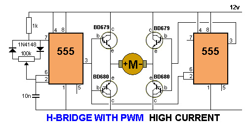
H-Bridge
For a project such as a robot or car, an electronic circuit is required, controlled by a control circuit. This control circuit outputs signals to manage an H-Bridge. The circuit includes a Hex Bug design, where the control circuit is...
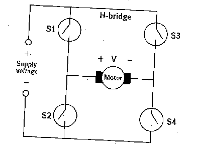
h-bridge circuitry
A microprocessor cannot drive a motor directly since it cannot supply enough current. Instead, an interface circuit is required so that the motor power is supplied from another source, with only control signals derived from the microprocessor. This interface can...
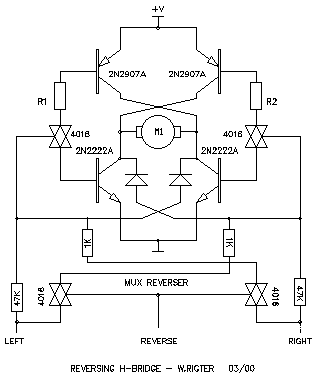
Wilf Rigter`s reversing H-bridge
This H-bridge variant was one of the first in which the reversing circuitry is built into the driver, rather than (as is more-commonly done) into the control circuitry upstream of the driver. This is a handy circuit, though, for 2-motor...
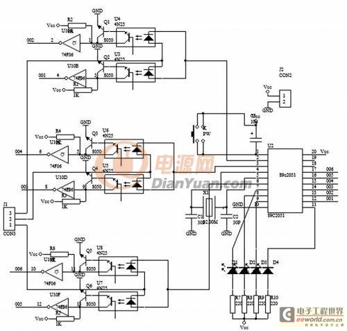
The low-powered BJT base pin cast differentiates the circuit cipher scheme automatically
In electronic technology, the triode utilizes a variety of general components and parts. The parameters of the triode and numerous electrical parametric measurement schemes are closely related to measurement results. Therefore, in electronic design, the base pin, typological judgment, and...
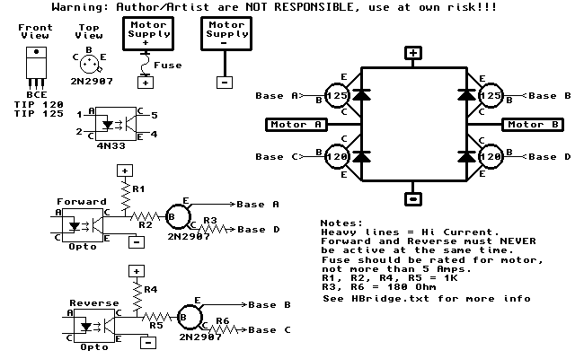
H-Bridge
The HandyBoard operates both pads using the positive supply from the battery. When one of the motors is intended to turn, the HandyBoard activates the corresponding pin to 0V. The voltage difference between the two pads causes the motor to...
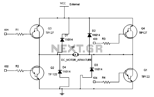
The H-Bridge Circuit Control Design in DC Motor Application
To maintain a constant speed of the motor under varying load conditions, a control application circuit is required. An H-Bridge circuit can be utilized to manage both the speed and direction of the motor. The accompanying diagram illustrates the H-Bridge...
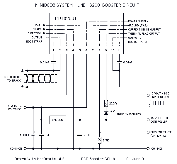
H Bridge Direct Current Motor Control Circuits
This page features H-Bridge circuits used for controlling direct current motors. Several designs are shown using both CMOS and Bi-Polar power devices. These circuits could be used as the basis for Model Railroad DCC Boosters or PWM motor controllers. The...
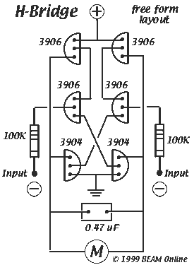
6-transistor H-bridge
Mark Tilden's 6-transistor H-bridge Design, limitations, usage
This is the six transistor "Tilden style" H-bridge; while not as old as the original "basic H-bridge," this goes "way back," and is the basis for many BEAM driver circuits.
* Up to 800 mA...
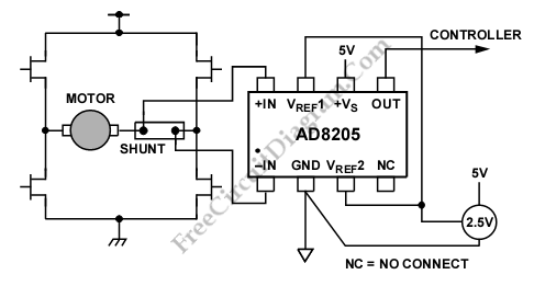
Differential Current Sensing Inside H Bridge
A differential current sensing circuit is integrated within an H-bridge configuration, as illustrated in the schematic diagram below. This circuit exemplifies the application of the AD8205, which is capable of measuring current in both directions as the motor changes direction...