
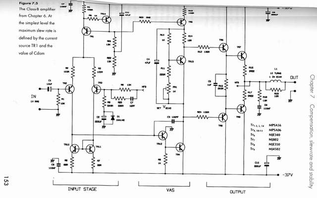
Class AB Transistor Power Amplifier

The discrete Class AB transistor audio power amplifier is designed to provide efficient amplification of audio signals while minimizing distortion. This circuit typically employs a pair of complementary transistors, one NPN and one PNP, to achieve the Class AB operation. The configuration allows the amplifier to conduct during both halves of the audio waveform, thus enhancing the linearity of the output signal.
Key components in this amplifier include the input coupling capacitor, which blocks any DC offset from the audio source, and biasing resistors that set the operating point of the transistors. A feedback network, often comprising resistors and capacitors, is utilized to stabilize the gain and improve frequency response. The output stage may include additional components such as emitter resistors to improve thermal stability and prevent crossover distortion.
The power supply section is crucial, as it provides the necessary voltage and current to drive the output transistors. Proper decoupling capacitors are often placed near the power supply pins to filter out noise and ensure stable operation under varying load conditions. Additionally, heat sinks may be employed on the transistors to dissipate heat generated during operation, ensuring reliability and longevity of the amplifier.
Overall, this Class AB amplifier design is favored for its balance of efficiency and sound quality, making it suitable for various audio applications, from home audio systems to professional sound reinforcement.Discrete Class AB Transistor Audio Power Amplifier Circuit Diagram This is a class AB transistor power amplifier. It is a simple amplifier to. 🔗 External reference
Related Circuits
This article is intended for individuals interested in constructing their own car amplifier. The fundamental calculations will be discussed below. Understanding these concepts will enable the construction of a car amplifier independently. The challenge in designing a car power...
Features: 1.3-12.2 V, 1 A, over-current protection. This is a simple but reliable device based one of the oldest integrated voltage regulators of them all - the LM723. The LM723 voltage regulator is a versatile and widely used component in...
This is a handy, easy to build general purpose 50 watt amp. The amp has an input for a radio, TV, stereo or other line level device. It also has a phono input for a record player, guitar, microphone...
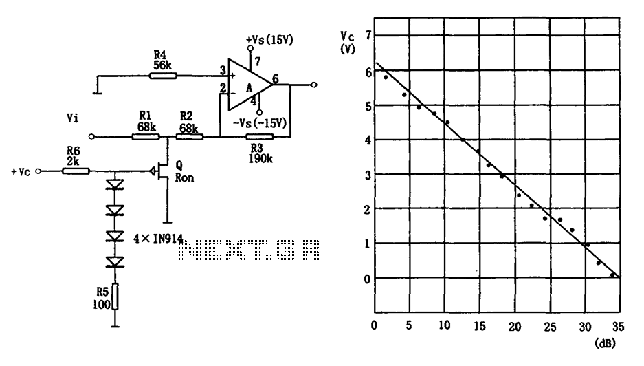
The voltage-controlled gain amplifier utilizes a FET gate voltage and the drain-source resistance (RSD) to approximate a logarithmic relationship. The integrated circuit chip LM307 is employed in the amplifier circuit with the inverting input configuration. In the circuit, RSD...
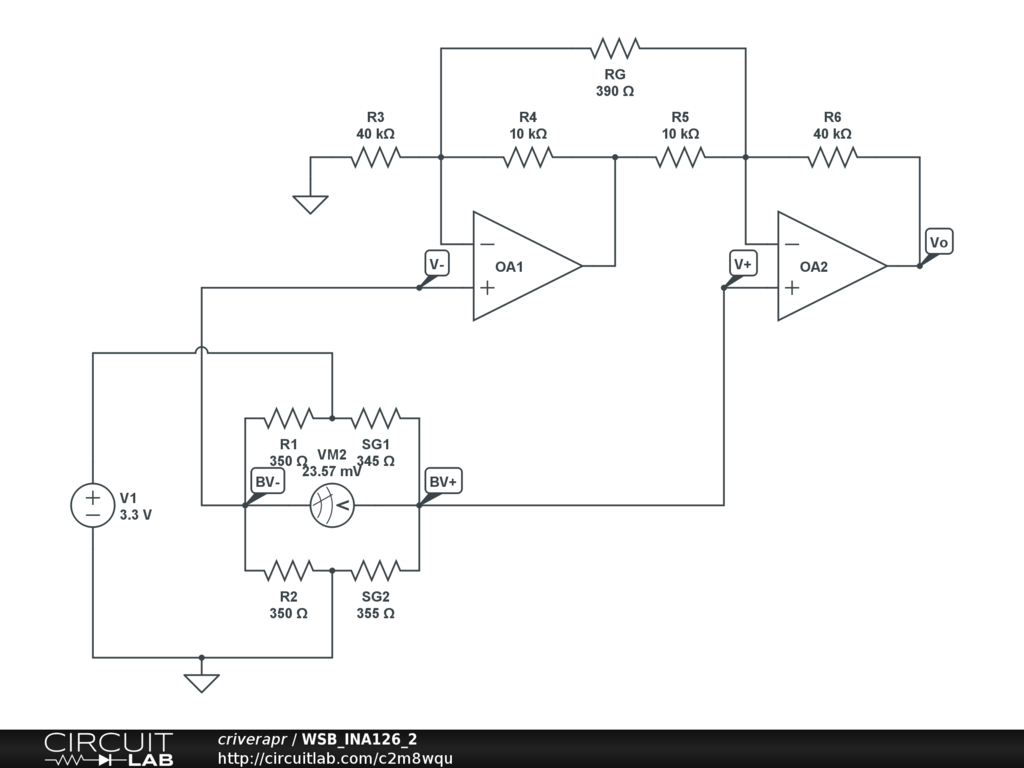
A half-bridge setup is utilized with strain gauges and an INA126 to amplify the voltage. The voltage can be read accurately when the lever is bent in one direction; however, no reading is obtained when the lever is bent...
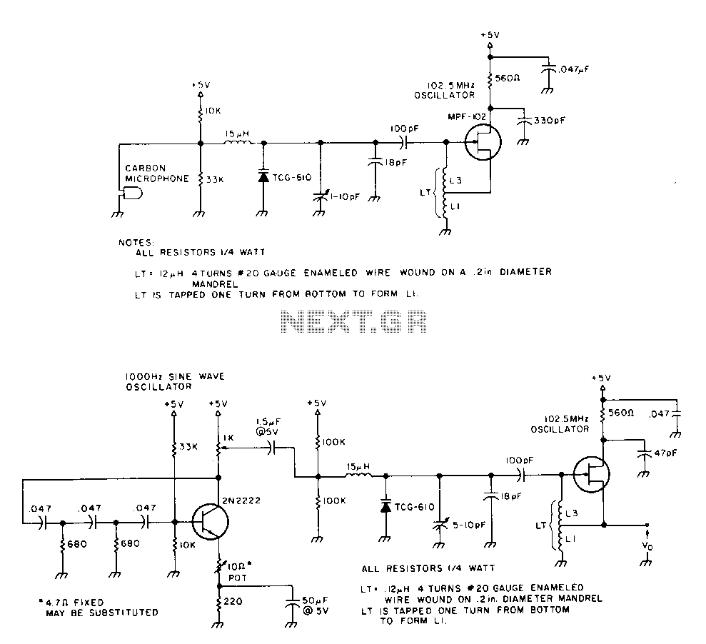
The 2N2222 circuitry is a three-element, phase-shift oscillator circuit designed to produce a 1,000 Hz sine wave. This sine wave is applied to the TCG-610 varactor diode, which has a capacitance of 6 pF at 4 V. This application...