


dc motor control using 555 timer circuit
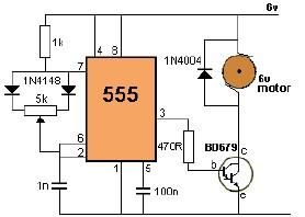
Description: This project utilizes a 555 timer to control the speed of a 6-volt DC motor. Speed adjustment is achieved by rotating a 50 kΩ potentiometer either to the left or right.
The circuit employs a 555 timer configured in astable mode to generate a pulse-width modulation (PWM) signal. This PWM signal is then used to control the average voltage supplied to the DC motor, thus regulating its speed.
The 555 timer's duty cycle can be adjusted by changing the resistance of the potentiometer, which in turn alters the width of the pulses generated. The motor is powered by a 6-volt supply, and the output from the 555 timer is fed into a transistor that acts as a switch. The transistor amplifies the PWM signal, allowing it to drive the motor effectively.
Key components of the circuit include the 555 timer IC, a 50 kΩ potentiometer, a suitable NPN transistor (such as the 2N2222), a diode for flyback protection, and the 6-volt DC motor. The diode is connected in reverse parallel with the motor to protect the circuit from voltage spikes generated when the motor is turned off.
The schematic representation of this circuit should include the connections between the 555 timer, the potentiometer, the transistor, the motor, and the power supply, ensuring that all components are properly oriented and connected to allow smooth operation. This design provides a straightforward method for controlling DC motor speed in various applications.Using this 555 timer DC motor control electronic project you can control speed of a 6 volts DC motor, by simply rotate left or right the 50 k potentiometer.
The circuit employs a 555 timer configured in astable mode to generate a pulse-width modulation (PWM) signal. This PWM signal is then used to control the average voltage supplied to the DC motor, thus regulating its speed.
The 555 timer's duty cycle can be adjusted by changing the resistance of the potentiometer, which in turn alters the width of the pulses generated. The motor is powered by a 6-volt supply, and the output from the 555 timer is fed into a transistor that acts as a switch. The transistor amplifies the PWM signal, allowing it to drive the motor effectively.
Key components of the circuit include the 555 timer IC, a 50 kΩ potentiometer, a suitable NPN transistor (such as the 2N2222), a diode for flyback protection, and the 6-volt DC motor. The diode is connected in reverse parallel with the motor to protect the circuit from voltage spikes generated when the motor is turned off.
The schematic representation of this circuit should include the connections between the 555 timer, the potentiometer, the transistor, the motor, and the power supply, ensuring that all components are properly oriented and connected to allow smooth operation. This design provides a straightforward method for controlling DC motor speed in various applications.Using this 555 timer DC motor control electronic project you can control speed of a 6 volts DC motor, by simply rotate left or right the 50 k potentiometer.
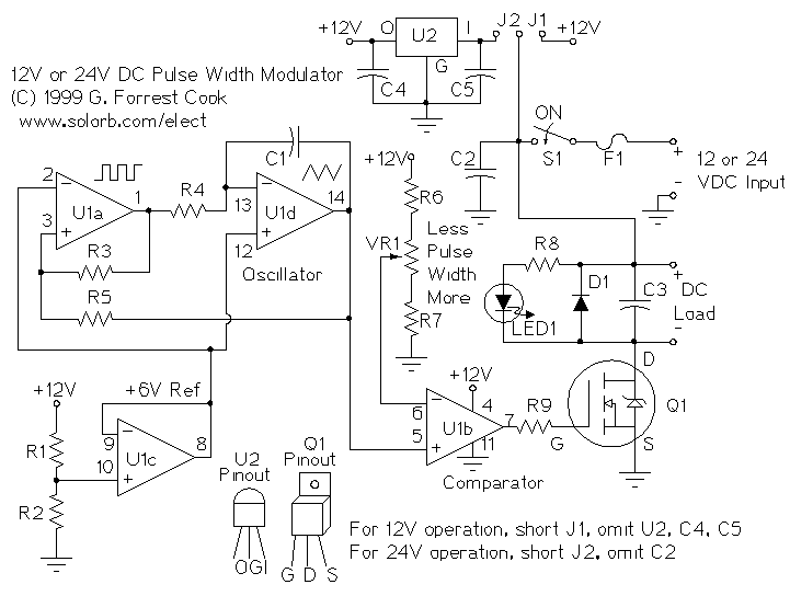
PWM Motor Speed Controller
A pulse width modulator (PWM) is a device that may be used as an efficient light dimmer or DC motor speed controller. The circuit described here is for a general purpose device that can control DC devices which draw up...
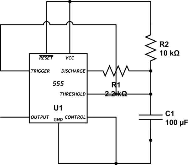
pcb design Need second set of eyes on 555 50% duty cycle soldered protoboard
Bold lines indicate soldered connections, while arrows represent wire-based connections. Red indicates V_cc, black represents ground, blue signifies intermediate connections, and gold denotes the primary output. Pins 1 and 5 are connected to ground. It is noted that pin 5...
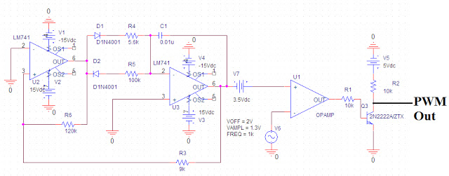
pulse width modulation
Pulse Width Modulation (PWM) is a highly efficient control scheme utilized to regulate the flow of power through various electronic devices. It is commonly found in switched-mode power supplies, LED dimming circuits, and variable speed motor controls, among other applications....
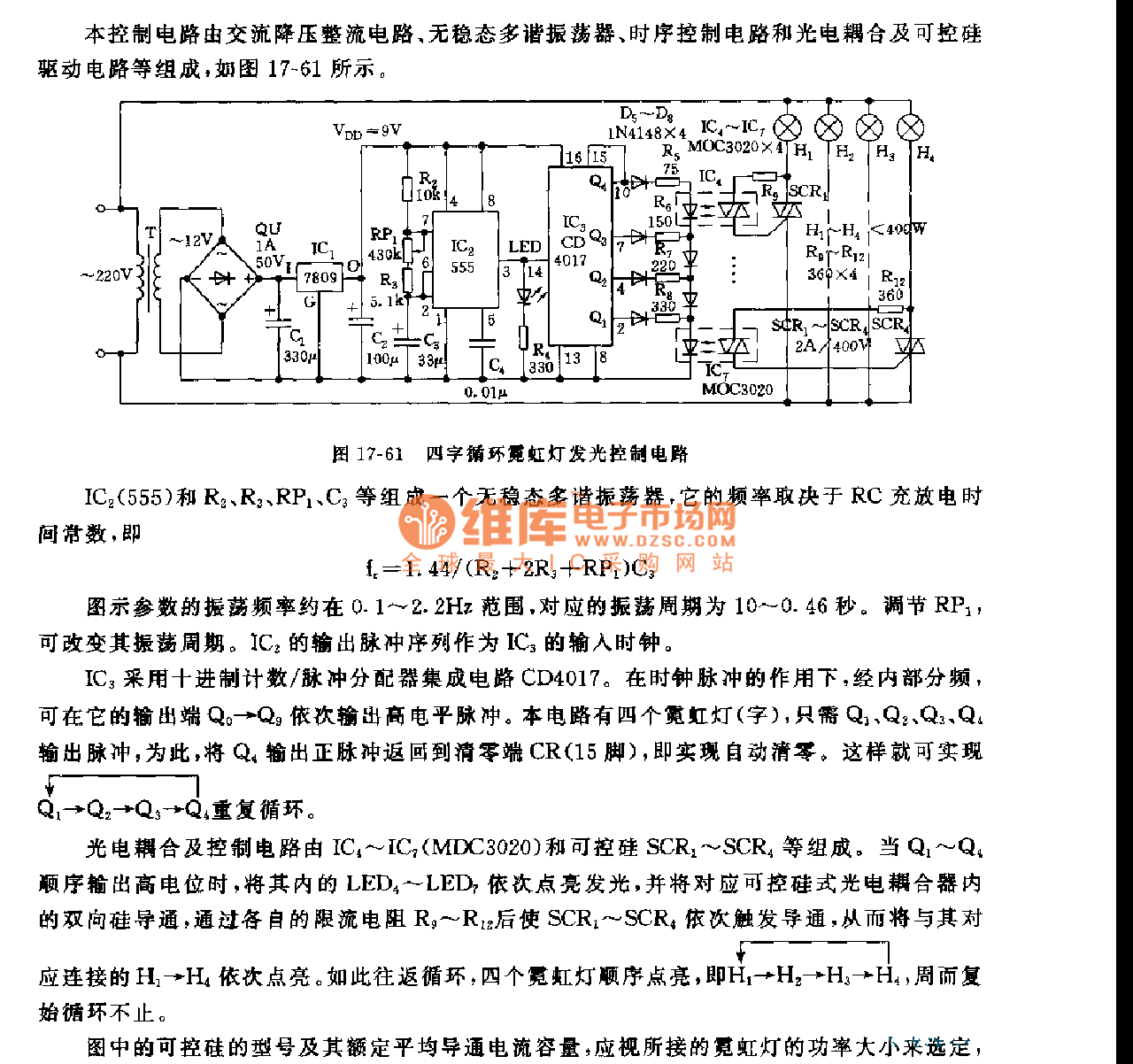
555 four words cycle neon light light control circuit
This control circuit consists of an AC step-down rectifier circuit, an astable multivibrator, a timing control circuit, an optocoupler circuit, and an SCR driving circuit, as illustrated in Figure 17-61. The astable multivibrator is formed using IC2 (555), resistors R2,...
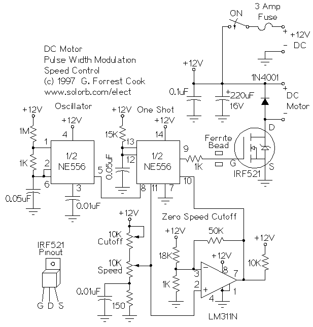
PWM DC Motor Speed Control
This is a circuit for controlling the speed of small DC motors; it works nicely as a speed controller for an HO or N gauge model railroad. More: The left half of the 556 dual timer IC is used as...
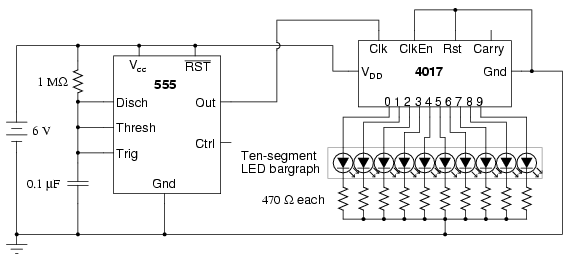
Schematic Diagram Of LED Sequencer Based On The 555 Timer IC
The following circuit illustrates a schematic diagram of an LED sequencer. This circuit is based on the 555 timer integrated circuit (IC). Features include a 555 timer circuit designed to debounce a mechanical switch, a 555 timer circuit to generate...
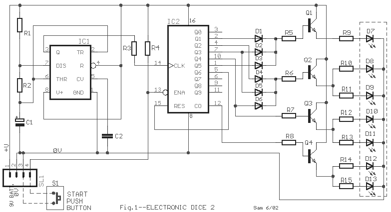
Electronic Dice circuit
The IC1 is a 555 timer IC configured for astable operation, generating clock pulses that are fed to IC2 through a 10K resistor. IC2 is a 10-stage counter, with output 6 (pin 5) connected to RESET (pin 15), resulting in...
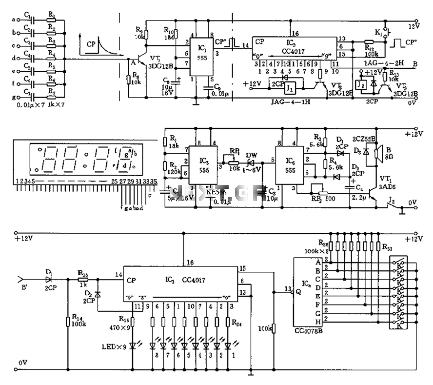
555 Anti-night sleep control circuit diagram recorder
This circuit is primarily designed as a timely reminder system for monitoring individuals on duty who may fall asleep. It features a detection circuit that processes minute signals. As the LED digital electronic timing clock displays the minute, the characters...
Serial DRAM non voltizer
This device includes a ringing generator and a tone oscillator. The tone oscillator is configured to operate at either 350 Hz or 440 Hz. The ringing generator is a sealed module providing 86 Vac at 20 Hz. Upon application of...