
Full Bridge Inverter with MOSFET and IR2110 gate driver

The grid-connected inverter is a crucial component in renewable energy systems, particularly in solar photovoltaic (PV) applications, where it converts the direct current (DC) generated by solar panels into alternating current (AC) that can be fed into the electrical grid. The full bridge inverter configuration is favored for its efficiency and ability to provide a high-quality output waveform.
In a full bridge inverter circuit, four switches (typically MOSFETs or IGBTs) are arranged in a bridge configuration. The operation involves alternating the conduction states of these switches to produce the desired AC output voltage. The control strategy is essential for achieving a sinusoidal output waveform and maintaining grid synchronization. Techniques such as pulse width modulation (PWM) are commonly employed to regulate the output voltage and frequency.
The inverter must also include protective features such as overcurrent protection, voltage clamping, and thermal management to ensure reliable operation. Additional components such as inductors and capacitors may be incorporated to filter the output waveform and reduce harmonic distortion.
Furthermore, the inverter should be designed to comply with grid connection standards, which may include requirements for anti-islanding protection, power factor correction, and maximum power point tracking (MPPT) to optimize energy harvesting from the solar panels.
Overall, the design of a grid-connected full bridge inverter involves a careful selection of components, control strategies, and protective measures to ensure efficient and safe integration with the electrical grid.This is my first post here, i need help on my final year project to make a grid connected inverter. For the full bridge inverter circuit i planned to.. 🔗 External reference
Related Circuits
The operational amplifier Wien-bridge oscillator offers insight into classic oscillator design through feedback analysis. Feedback analysis determines whether a circuit is stable or unstable. In amplifier design, particularly for high-speed applications, avoiding conditions that lead to oscillation is crucial....
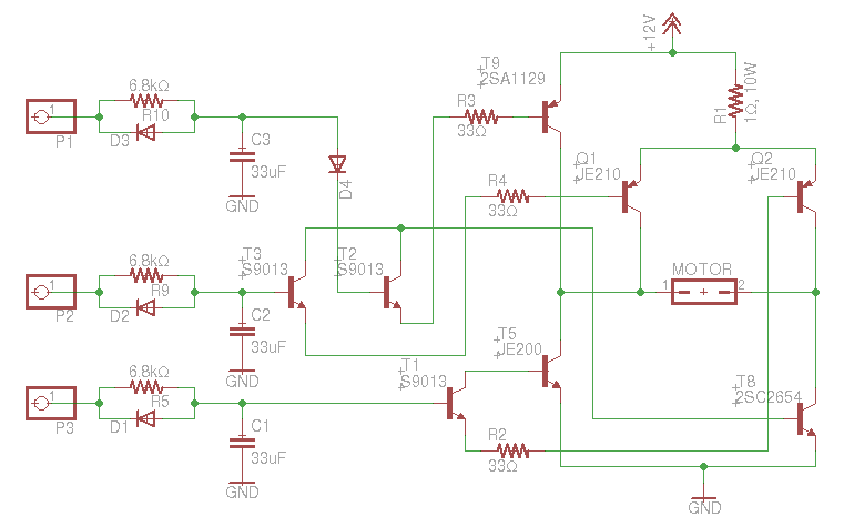
An old RC car is available, but it lacks the transmitter. A custom receiver/transmitter has been built using a microcontroller and a 2.4 GHz transceiver. However, there is uncertainty regarding the functionality of the car's original H-Bridge circuit. The H-Bridge...
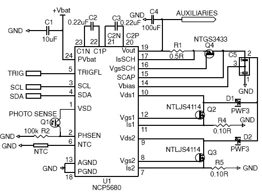
This white LED driver circuit project utilizes the NCP5680 high-efficiency white LED driver integrated circuit (IC). The NCP5680 supports dual power flash LED and torch operations. Its built-in DC/DC converter employs a highly efficient charge pump structure with operating...
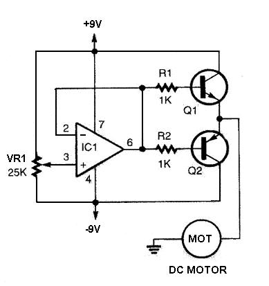
The DC motor driver circuit depicted in the images can be utilized for controlling DC motors, allowing for bidirectional rotation and adjustable speed. This straightforward circuit is constructed using a 741 operational amplifier (op-amp) as a voltage comparator, along...
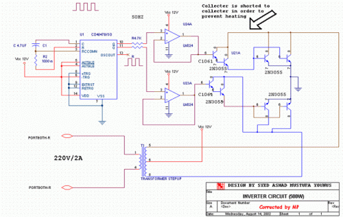
This circuit converts 12V DC into 220V AC. It utilizes a 4047 integrated circuit to generate a 50Hz square wave, which is then used to amplify the current and subsequently increase the voltage using a step-up transformer. The circuit...
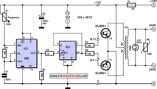
Although modern electrical appliances are increasingly self-powered, particularly portable ones used for camping or summer holidays, a source of 230 V AC is sometimes necessary. When the power requirement remains relatively low—30 VA in this case—it is straightforward to...