
HF linear amplifier circuit
The power amplifier output Pi section is a critical component in high-frequency RF applications, where precise tuning and efficient power transfer are essential. The use of variable capacitors allows for fine-tuning of the circuit to achieve optimal performance across different frequency bands. The custom capacitor's design, activated by a relay, enhances versatility, enabling the amplifier to operate effectively in lower frequency ranges.
The anode choke serves to stabilize the high-voltage output, ensuring that the circuit maintains a consistent performance under varying load conditions. The choice of materials, such as the PTFE tube for the choke, is important for maintaining insulation and minimizing losses. The connection between the choke and the doorknob capacitor through a brass ferrule ensures a robust mechanical and electrical link, which is essential for high-power applications.
Airflow management within the grid compartment is crucial for thermal regulation, as excessive heat can lead to component failure. The design allows for effective cooling, with the fan facilitating airflow that aids in dissipating heat generated during operation. The strategic placement of holes around the grid bases ensures that air is efficiently channeled through the PA chimneys, promoting optimal thermal performance.
The heater and cathode connections, made from brass strips, are chosen for their low resistance and good conductivity, essential for maintaining the reliability of the heating circuit. The bifilar winding of the heater choke on a ferrite rod enhances inductance while minimizing electromagnetic interference, which is particularly important in RF circuits.
The inclusion of a non-inductive resistor in the input circuit is a standard practice to prevent reflections and ensure a smooth impedance match. The 100-ohm value aligns with the grid load, optimizing the input VSWR and enhancing the overall efficiency of the amplifier. This careful consideration of component selection and circuit design contributes to a robust, high-performance power amplifier suitable for demanding RF applications.The PA output Pi section consists of 2 variable Cs (20 - 120pF and a second (home made) 50 - 450pF switched in for the lower bands by a simply modified 12v power relay). The anode choke (200t, 24swg 5" long on 1" dia PTFE tube stock) is mounted directly onto a 3300pF 10kV doorknob capacitor using a small turned brass ferule.
The grid compartment. The main fan blows into the sealed grid compartment, and exits through holes around the grid bases to flow through the PA chimneys. The heater/cathode connections are again made from thin brass strip. The heater choke is wound on ferrite rod (from a scrap transistor radio, bifilar 28t 10swg). The input circuit consists of a 100ohm non-inductive 50Watt resistor (Farnell - about £3) directly across the input.
The grid load is also about 100ohm under normal operating conditions so the input VSWR should be quite good. 🔗 External reference
Related Circuits
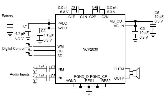
The NCP2830 audio power amplifier features high-quality audio performance with a total harmonic distortion plus noise (THD+N) of 0.04%. It offers low noise with a signal-to-noise ratio (SNR) of up to 100 dB and optimizes overall system efficiency, achieving...
How the processor produces 3 as the output. This question may be challenging to answer in simple terms. If so, a link to a book would be helpful. The process by which a processor generates the output of the number...
The Zen single-ended MOSFET amplifier was published by Nelson Pass in The Audio Amateur. In a subsequent issue of this magazine, Nelson slightly improved the original design. The "Revisited" version includes the following circuit modifications: 1. More extensive power supply...
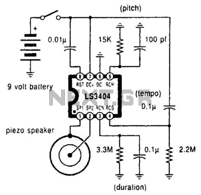
A high-quality melody circuit produces a slow decay waveform that generates chime-like notes. The pitch, tempo, and duration of the notes are all adjustable. The melody circuit is designed to offer a versatile sound generation capability, making it suitable for various...
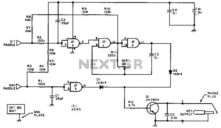
This keyer utilizes skin conductivity to emulate the traditional mechanical CW bug keyer. When the dit paddle is activated, the bias on the inverter, IC1-a, is routed to ground, resulting in a logic high output. This triggers oscillator sections...
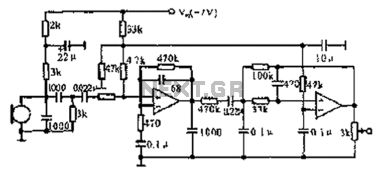
The CX9800 models of mobile phones and desktop PCs feature a high-performance voice processing circuit that compresses the amplitude and bandwidth of the microphone signal. This design enhances the sensitivity of the microphone and its adaptability to varying distances....