
Hydrogen Generator 555 Timer Pulse Width Modulation Circuit
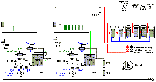
The hydrogen generator circuit utilizing a 555 timer operates by controlling the duty cycle of the PWM signal to regulate the electrolysis process. The 555 timer is configured in astable mode, producing a continuous square wave output. This output is fed to an electrolytic cell, where water (H2O) is split into hydrogen (H2) and oxygen (O2) gases through the application of an electric current.
The circuit design includes the following components: a 555 timer IC, resistors, capacitors, and an electrolytic cell consisting of two electrodes submerged in water. The resistors determine the frequency and duty cycle of the PWM signal, while the capacitor helps in stabilizing the output waveform. The duty cycle can be adjusted by varying the values of the resistors, enabling the user to control the amount of hydrogen produced.
Power supply requirements for the circuit typically range from 5V to 15V, depending on the specific design and components used. The electrolytic cell must be constructed from materials that are resistant to corrosion, such as stainless steel or graphite, to ensure longevity and efficiency.
Safety precautions should be taken when working with hydrogen, as it is highly flammable. Adequate ventilation is necessary, and the circuit should be housed in a non-combustible enclosure to prevent any fire hazards. The generated hydrogen can be collected and utilized for various applications, including fuel cells or combustion engines, demonstrating the practical utility of this PWM-controlled hydrogen generator circuit.How to Make a Hydrogen Generator 555 Timer Circuit PWM. This Pulse Width Modulation (PWM) Circuit could Produce Hydrogen on Demand.. 🔗 External reference
Related Circuits
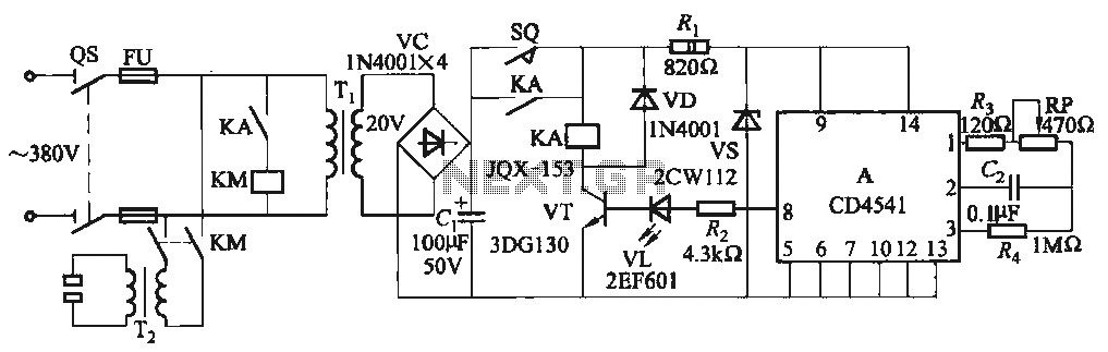
One Foot Spot Welder circuit. The circuit utilizes the IC CD4541 to provide precise delay characteristics, enabling the electrical time constant necessary for effective welding. This ensures consistent welding quality across identical weldments. For varying weldments, the electrical locator...
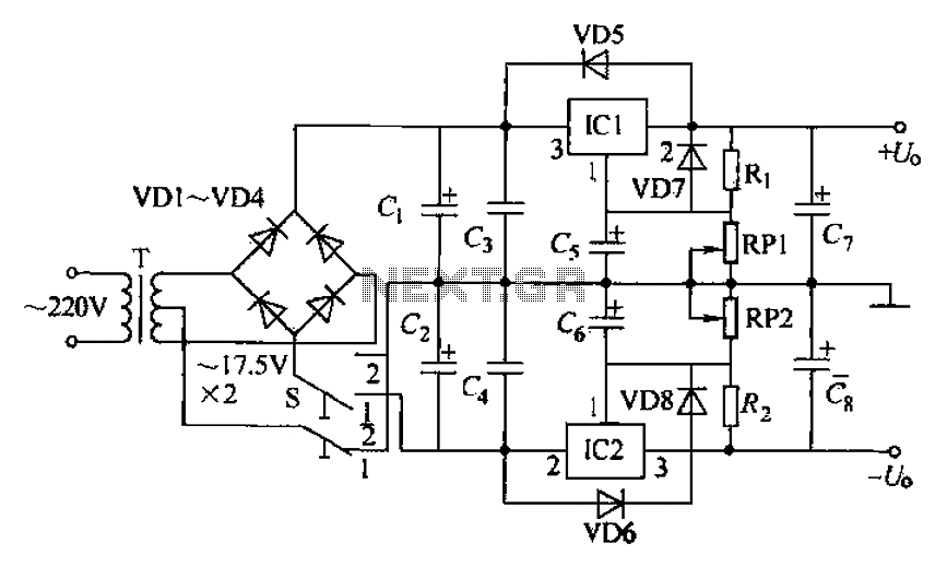
The circuit utilizes a three-terminal adjustable integrated voltage regulator. It includes a gear set and a power supply voltage that is stepped down using a transformer rated at 17.5V x 2 AC. The output voltage after the bridge rectifier...
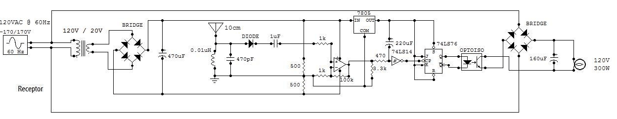
This circuit is a 73 MHz halogen lamp radio-controlled system. Its purpose is to control the power state of a halogen lamp using a remote control. When the push button on the remote control is pressed, the power state...
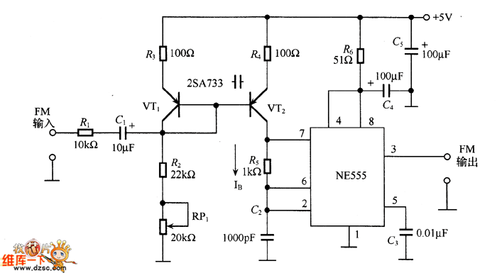
The figure illustrates an NE555 frequency modulation (FM) circuit. In this circuit, pin 7 of the NE555 is connected to an FM modulation section that consists of resistor R5 and capacitor C2, although the frequency range is somewhat limited....
The project involves the development of a miniature transmitter suitable for implantation in a rat's body, capable of transmitting 416-bit data samples at a rate of 400 samples per second. It is designed to have a detection range of...
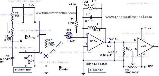
All components used in the Moving Sensor/Detector Schematic Diagram utilize the IC NE555 and the Phototransistor L14F. The primary component in this circuit is the IC NE555, along with an IR LED, the Phototransistor L14F, and the IC LM1458....