
Microcontroller Unit Co-Simulation for SPICE-Based Circuits in NI Multisim

The integration of microcontroller units (MCUs) within the National Instruments Multisim environment enhances the simulation capabilities for both educational and professional applications. This feature allows users to seamlessly incorporate MCUs into their circuit designs, facilitating a comprehensive understanding of embedded systems and digital electronics. The support for popular microcontroller architectures, such as the Intel®/Atmel® 8051/8052 and Microchip PIC16F84A, broadens the scope for users to experiment with a variety of applications and peripherals.
In the context of the provided tutorial, the project exemplifies a fundamental application of the PIC16F84A microcontroller, demonstrating its functionality through a simple counter mechanism. The configuration of Port A as an input interface connected to two switches allows for user interaction, while Port B's output configuration to a 7-segment display provides a visual representation of the counting process. This setup not only illustrates basic input/output operations but also serves as a platform for students to learn about programming techniques in both assembly and C languages.
The MCU Module's design supports a modular approach, where multiple projects can coexist within a single workspace, allowing for comparative analysis between different programming methodologies. The ability to switch between assembly and C code projects further enriches the learning experience, enabling users to appreciate the nuances and efficiencies of each programming paradigm. The detailed instructions provided in the tutorial ensure that users can replicate the project effectively, fostering hands-on learning and practical skills in microcontroller programming and circuit design.National Instruments Multisim now has microcontroller unit co-simulation capabilities, allowing you to include a microcontroller, programmed in assembly or C code, within your SPICE modeled circuit. The MCU functionality in Multisim enables students, educators and professional users to program MCU`s in assembly or C language within the familiar Multisim environment.
The MCU capability can be used with any of Multisim`s virtual instruments for a complete system simulation, including the microcontroller and all connected analog and digital SPICE components. The MCU Module supports Intel ®/Atmel ® 8051/8052 and Microchip PIC16F84a chips as well as a broad range of advanced peripherals like external RAM and ROM, keypads, graphical and alphanumeric LCDs and others.
The MCU Module takes full advantage of the Multisim educational platform which makes it the ideal choice for courses such as digital electronics, computer architecture, MCU programming, embedded control, senior design and more! The attached archive contains all files necessary to complete this tutorial. However, this tutorial is showing how to create an MCU Module project from scratch, with the exception of source files.
The MCU project used in this tutorial uses a PIC16F84 from Microchip to demonstrate a simple up and down counter. Port A of the microcontroller is configured for input and connected to two switches. Port B is configured as output and connected to a 7-segment displays. The switches are used to turn the display on and off and change counting direction. The 7-segment display shows the current counter value (0-F). This MCU Module example consists of two identical projects. One build with assembly and one with C code. Use the following components to complete the circuit as shown below. All components can be used with their default settings. If you like to view the default settings, right click on any component and select properties. A MCU Module workspace can have multiple projects that can consists of assembly or C code source files.
If you like to repeat the steps above, set the project C Code Project as active MCU project. 🔗 External reference
Related Circuits

The LED running light project can be easily implemented using microcontrollers, particularly the Microchip PIC microcontroller. This project utilizes the PIC16F877A microcontroller, which features a 40-pin IC configuration, with LEDs connected to port B. The LEDs twinkle in accordance...
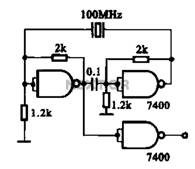
Crystal oscillator integrated circuits, specifically two diagrams of oscillator circuits with oscillation frequencies of 10 MHz and 20 MHz. Crystal oscillators are essential components in various electronic applications, providing stable frequency references for timing and synchronization purposes. The circuits presented...
A brief history: Like many tutorials, this one begins with a historical overview. However, it must be noted that there is limited background information available regarding the development of 7-segment displays. 7-segment displays are widely used electronic components that...
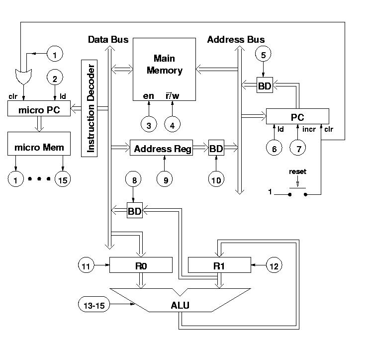
The diagram features a micro memory capable of storing up to 64 different addresses, each containing 15 bits, referred to as micro operations (MOPs). These MOPs govern all functions of the computer. Adjacent to the micro memory is the...
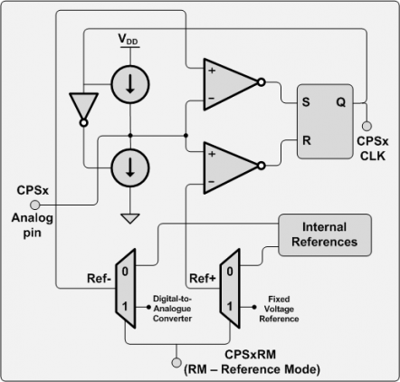
There are numerous applications for this hardware, including touch pads, proximity sensors, capacitive sensor readouts, high-precision capacitance measurements, ultra-small capacitance change detection, soil moisture sensing, and skin moisture measurement, among others. However, after searching for examples, it was surprising...
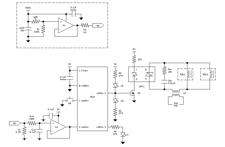
While discussing an all-linear automatic night light circuit, it was mentioned that an MCU-based Automatic Night Light Controller (ANLC) was being tested. The firmware has been tweaked since then. Recently, the sensor was installed outdoors and connected to control...